
Backlight module

A backlight module and light source technology, applied in the field of heat dissipation structure, can solve the problems of light guide plate deflection, uneven heat dissipation, high thermal resistance, etc., to avoid the generation of local hot spots and solve the effect of uneven heating and deflection

Inactive Publication Date: 2012-02-15
AU OPTRONICS CORP
View PDF2 Cites 7 Cited by
  • Summary
  • Abstract
  • Description
  • Claims
  • Application Information

AI Technical Summary

Problems solved by technology

However, due to the long heat conduction path and high thermal resistance of this heat dissipation method, it is easy to cause uneven heat dissipation and local hot spots, thus causing the light guide plate to bend and deform.

Method used


Image

  • Backlight module
  • Backlight module
  • Backlight module

Examples


Embodiment Construction

[0018] The following will clearly illustrate the spirit of the present invention with the accompanying drawings and embodiments. After any person skilled in the art understands the preferred embodiments of the present invention, they can be changed and modified by the technology taught by the present invention without departing from it. Spirit and protection scope of the present invention.

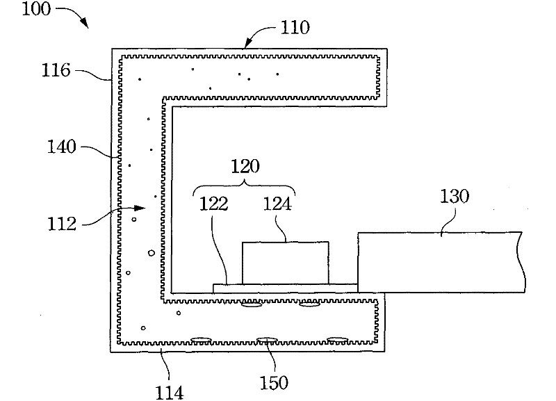
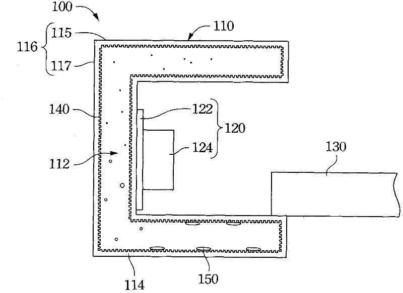
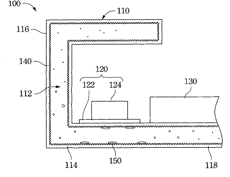
[0019] refer to figure 1 , is a partial cross-sectional view illustrating the first embodiment of the backlight module of the present invention. The backlight module 100 includes a bracket 110 , a light source 120 disposed on the bracket 110 , and a light guide plate 130 located on one side of the light source 120 . The bracket 110 has a cavity 112 , and the cavity 112 is the interior of the whole bracket 110 . The backlight module 100 further includes a microcapillary structure 140 formed on the inner surface of the cavity 112 , and a fluid 150 located in the cavity 112 .

[0020] The ...


PUM


Abstract

A backlight module comprises a support provided with a cavity, a light source arranged on the support, a micro capillary structure formed at the surface of the cavity and a fluid arranged in the cavity.

Description

technical field [0001] The present invention relates to a backlight module, and in particular to a heat dissipation structure of the backlight module. Background technique [0002] Liquid Crystal Display (LCD) has the advantages of high image quality, small size, light weight, low voltage drive, low power consumption and wide application range, so it has been widely used in portable TVs, mobile phones, video recorders, etc. In consumer electronics or computer products such as video projectors, notebook computers, and desktop displays, displays have become the mainstream. [0003] A liquid crystal display mainly includes components such as a liquid crystal panel, a backlight module, and a frame. The backlight module is used to provide a light source, and mainly includes components such as a light source, a light guide plate, and a bracket. The liquid crystal panel and the backlight module are then assembled in the frame. [0004] The light source is the main heat source in...

Claims


Application Information

Patent Timeline
IPC IPC(8): F21S8/00F21V19/00F21V29/00F21V29/51
Inventor 江和兴
Owner AU OPTRONICS CORP
Learn More