
Flat-plate X ray detector and preparation method thereof

An X-ray and detector technology, applied in the field of flat panel X-ray detector exposure control and X-ray detectors, can solve the problems affecting the image quality of the flat panel X-ray detector and the reduction of the aperture ratio of the X-ray detector, etc.

Active Publication Date: 2013-12-25
SHANGHAI IRAY TECH
View PDF6 Cites 0 Cited by
  • Summary
  • Abstract
  • Description
  • Claims
  • Application Information

AI Technical Summary

Problems solved by technology

Since the area occupied by the photoelectric conversion element remains unchanged, the integration of the detection element will reduce the proportion of the area occupied by the photoelectric conversion element in the detection pixel, reducing the aperture ratio of the X-ray detector.
[0006] In addition, the detection element and the flat-panel X-ray detector that realize the AEC function are prepared on the same surface of the substrate, and the data transmission line of the detection element will cause crosstalk to the data transmission line of the flat-panel X-ray detector, which will affect the performance of the flat-panel X-ray detector. The resulting image quality

Method used


Image

  • Flat-plate X ray detector and preparation method thereof
  • Flat-plate X ray detector and preparation method thereof
  • Flat-plate X ray detector and preparation method thereof

Examples


Embodiment 1

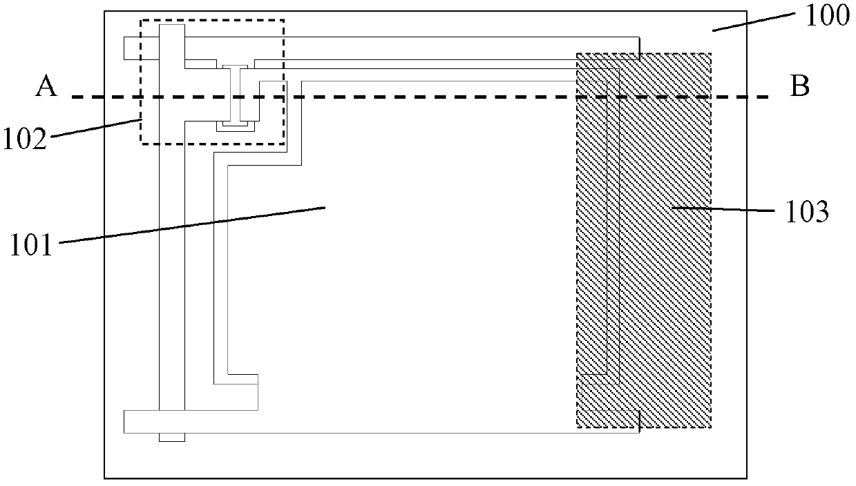
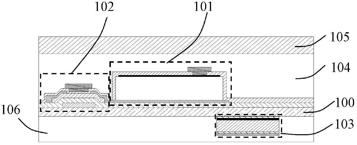
[0043] The detection element in this embodiment adopts PIN photodiode, see figure 1 , is a schematic top view of the flat-panel X-ray detector in this embodiment. The upper surface of the glass substrate 100 includes a detection pixel, and the detection pixel includes a PIN photodiode 101, a TFT 102 and a light-transmitting element-free area. The lower surface of the glass substrate includes a detection element 103 , and the area covered by the detection element 103 includes a part of the lower surface of the upper surface photoelectric conversion element PIN photodiode covering the substrate and a lower surface of the substrate in an element-free area. In order to make the schematic representation of this embodiment more clearly, see figure 2 ,yes figure 1 In the cross-sectional view along the line AB, the photoelectric conversion element PIN photodiode 101 and the control element TFT102 are located on the upper surface of the substrate 100, and the upper surface of the detec...

Embodiment 2

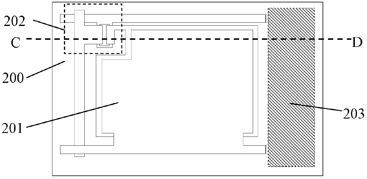
[0047] The detection element in this embodiment adopts PIN photodiode, see image 3 , is a schematic top view of the flat-panel X-ray detector in this embodiment, the upper surface of the glass substrate 200 includes a detection pixel, the detection pixel includes a PIN photodiode 201, TFT 202 and a transparent component-free area, and the lower surface of the glass substrate includes a detection pixel Component 203, the detection component 203 covers only the lower surface of the substrate in the component-free area of ​​the detection pixel. In order to make the schematic representation of this embodiment more clearly, see Figure 4 ,yes image 3 In the cross-sectional view along the line CD, the photoelectric conversion element PIN photodiode 201 and the control element TFT202 are located on the upper surface of the substrate 200, and the upper surface of the detector is covered by a dielectric layer 204, and above the dielectric layer is a scintillator that converts X-rays...

Embodiment 3

[0050] see Figure 5 , is a schematic top view of the flat-panel X-ray detector in this embodiment. The upper surface of the substrate 300 includes a plurality of detection pixels 301 (shown in dotted line boxes) for detecting X-rays, and the detection pixels include photoelectric conversion elements PIN photodiodes 302 . The control element TFT 303 and the element-free area, the detection element 304 is located on the lower surface of the substrate, and the detection element coverage area includes the lower surface of the substrate in the element-free area in the pixel 301 . In this embodiment, the upper surface of the substrate includes 9 pixels, and the lower surface of the substrate includes 1 detection element as an example. In an actual flat-panel X-ray detector, thousands of such pixels and multiple detection elements may be included. The detection element Usually distributed in a specific area in the pixel array of a flat-panel X-ray detector, such as Figure 6 L, R a...


PUM


Abstract

The invention provides a flat-plate X ray detector, which comprises a substrate, a photoelectric converting component, a control component and a detecting component, wherein the upper surface of the substrate comprises at least one detecting pixel; the detecting pixel comprises the photoelectric converting component, the control component and a light-transmission component-free area; the lower surface of the substrate comprises the detecting component; and a coverage area of the detecting component comprises the lower surface of a substrate in the component-free area in the detecting pixel on the upper surface. Correspondingly, the invention further provides a preparation method of the flat-pate X ray detector. The detecting components of the flat-plate X ray detector provided by the invention are prepared on the lower surface of the substrate; the pixel area of the detector is not increased; and therefore, the pixel aperture opening ratio cannot be decreased. Data transmission lines of the detecting components and a data transmission line of the flat-plate X ray detector are not on the same surface of the substrate, cannot generate cross talk to the data transmission line of the detector, and have no influence on the image quality obtained by the flat-plate X ray detector.

Description

technical field [0001] The invention relates to the field of X-ray detectors, in particular to the field of exposure control of flat-panel X-ray detectors. Background technique [0002] In the process of medical detection, in order to minimize the radiation dose received by patients while ensuring the quality of X-ray imaging, controlling the start and end of X-ray exposure is a very critical technology. The commonly used methods of controlling the start and end of X-ray exposure include: controlling the start and end of X-ray exposure manually by radiologists or electronic timers; controlling the termination of X-ray exposure by AEC (Automatic exposure control, automatic exposure control) equipment . [0003] AEC equipment is a device that controls the X-ray exposure time. Its function is to precisely control the X-ray exposure time under the premise of ensuring the quality of the X-ray image, so as to minimize the X-ray dose emitted to the patient. The signal generated b...

Claims


Application Information

Patent Timeline
Patent Type & Authority Patents(China)
IPC IPC(8): G01T1/08
Inventor 邱承彬刘琳
Owner SHANGHAI IRAY TECH
Learn More