

Output-side-switching-based dynamic power flow control device and control method for controllable transformer
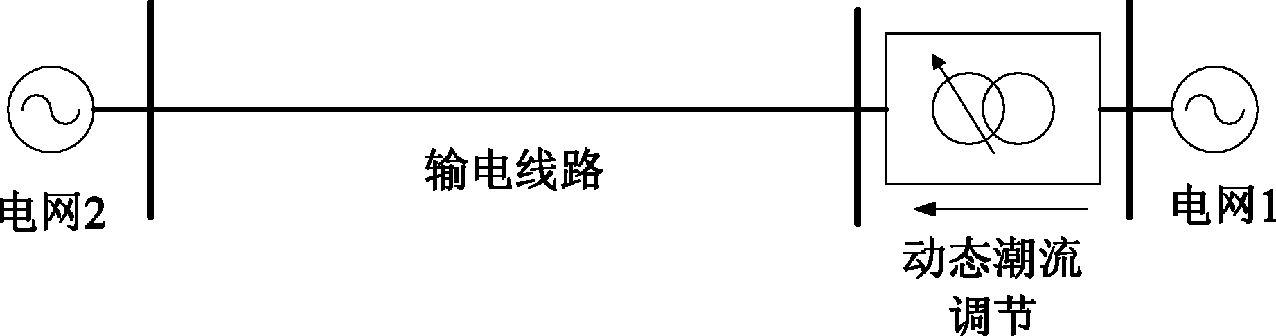
A dynamic power flow and control device technology, applied in the field of flexible power transmission, can solve problems such as large loss of FACTS devices, complex control structure, and system stability problems and limitations
- Summary
- Abstract
- Description
- Claims
- Application Information
AI Technical Summary
Problems solved by technology
Method used
Image

Examples
Embodiment Construction
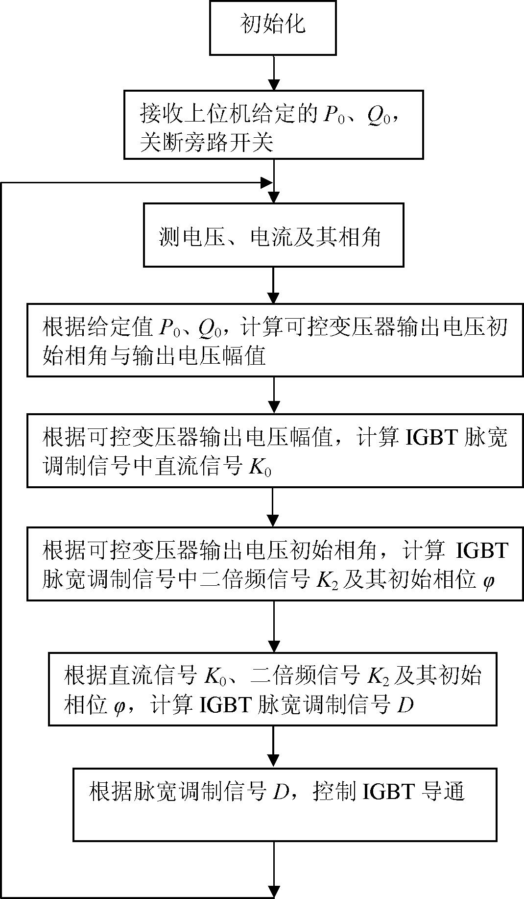
[0078] The present invention will be further described below in conjunction with the embodiments and accompanying drawings, but the protection scope of the present invention should not be limited thereby.
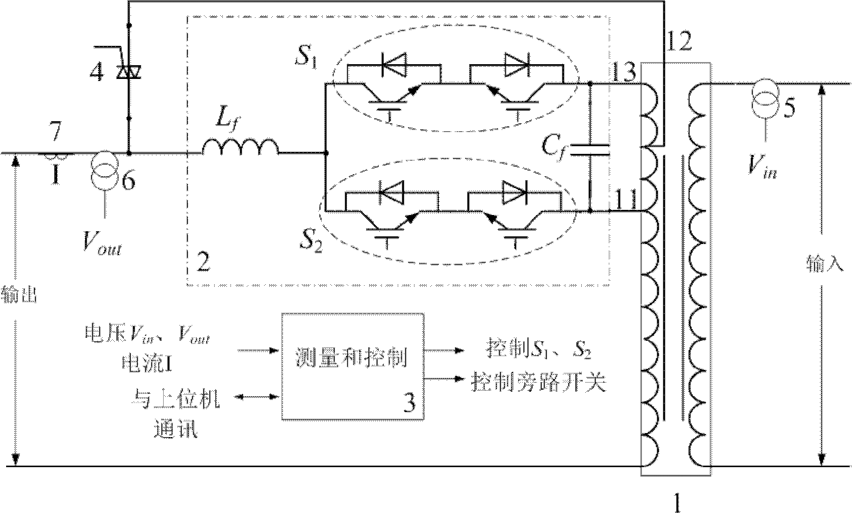
[0079] see first figure 1 , figure 1 It is a structural schematic diagram of the dynamic power flow control device based on the controllable transformer of the output side switch of the present invention. It can be seen from the figure that a dynamic power flow control device based on a controllable transformer with switches on the output side includes: a controllable transformer 1, a power unit 2, a measurement and control module 3, a bypass switch 4, an input voltage transformer 5, and an output voltage transformer. Transformer 6 and output current transformer 7 form:
[0080] The secondary side of the controllable transformer 1 includes a main connector 12 and a positive tap 13 and a negative tap 11;
[0081] The power unit 2 is composed of the first group of power tu...
PUM
 Abstract
Description
Claims
Application Information