
Calibration device, method, and program for onboard camera

A calibration device and camera technology, applied in optical observation devices, vehicle parts, transportation and packaging, etc., can solve the problems of unstable calibration accuracy and time required for calibration by operators

Active Publication Date: 2012-02-15
AISIN SEIKI KK
View PDF8 Cites 36 Cited by
  • Summary
  • Abstract
  • Description
  • Claims
  • Application Information

AI Technical Summary

Problems solved by technology

However, it takes time for the operator to adjust the three axes corresponding to the rotation of the camera by manually operating the adjustment buttons while looking at the monitor screen.
In addition, the calibration accuracy of the operator is unstable, and products with insufficient calibration may be sent to the subsequent process.

Method used


Image

  • Calibration device, method, and program for onboard camera
  • Calibration device, method, and program for onboard camera
  • Calibration device, method, and program for onboard camera

Examples


Embodiment Construction

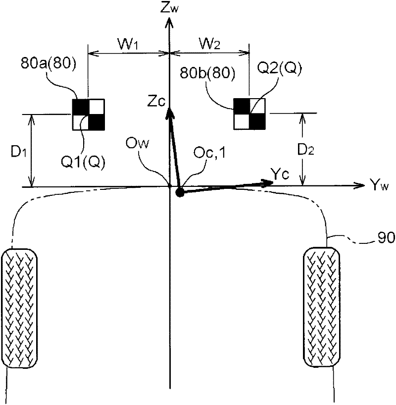
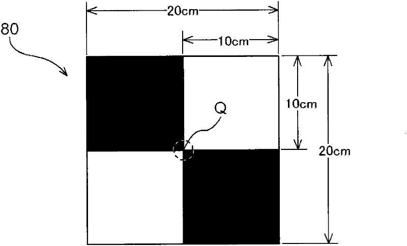
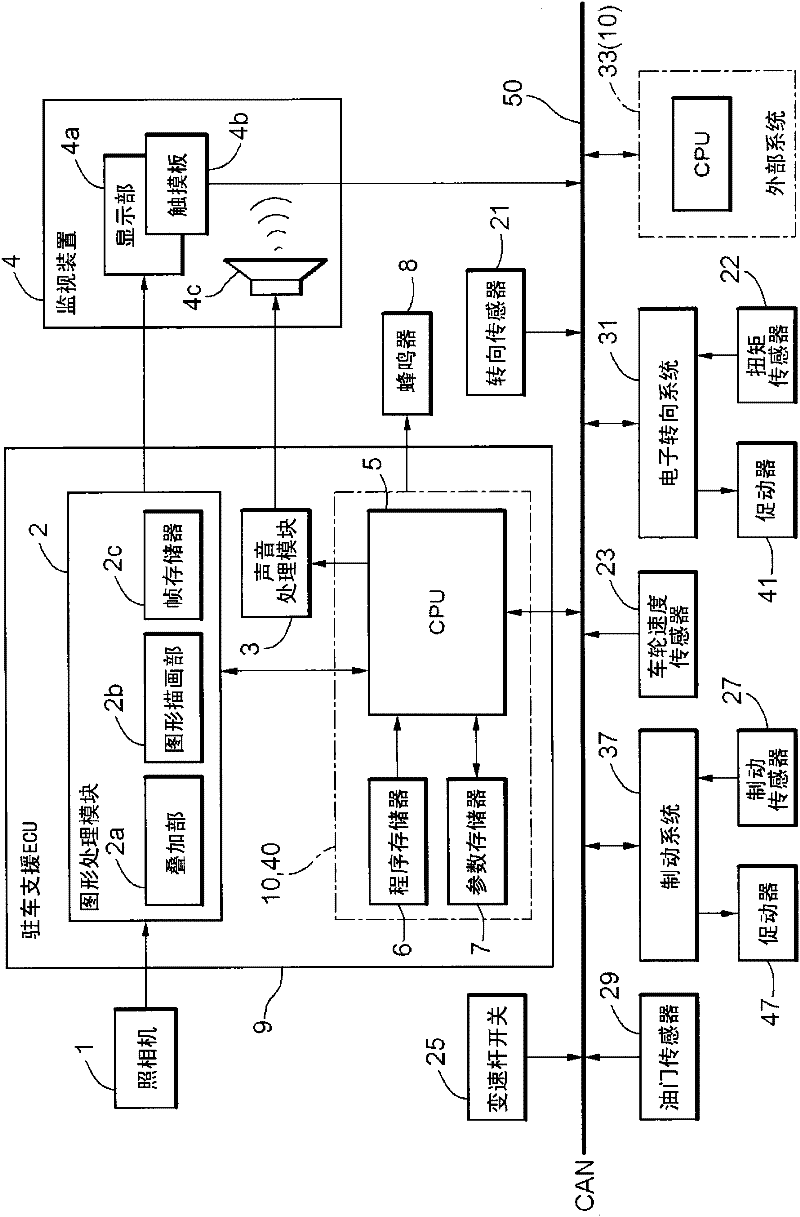
[0112] Next, an embodiment of the calibration device of the present invention will be described based on the drawings, taking as an example the calibration of the camera 1 (vehicle camera) that photographs the scene behind the vehicle 90 . The camera 1 (vehicle camera) is arranged behind the vehicle 90 above the license plate and at a position offset laterally from the vehicle axis, with its optical axis directed downward (for example, 30° downward from the horizontal). The camera 1 has, for example, a wide-angle lens with an angle of view of 110° to 120°, and can capture an area approximately 8 m behind. The camera 1 is calibrated for the purpose of absorbing mounting errors when it is mounted on the vehicle 9 in a vehicle production plant or the like. In addition, this correction is also used in a repair shop or the like to correct the deviation of the camera 1 due to the accumulation of running vibrations, impacts, and the like.

[0113] Such as figure 1 As shown, in thi...


PUM


Abstract

A high-productivity calibration device for an onboard camera, which can calibrate an onboard camera with good precision in a short amount of time and with a simple configuration. Based on the actual coordinates identified on the projection plane of the camera coordinate system and on the converted coordinates which were converted from the initial coordinates of calibration points using pre-finalized camera adjustment values, the adjustment values for the angles of rotation around one or two axes among the three axes of the camera coordinate system are computed and the camera adjustment values are updated. Then, based on the actual coordinates and on the converted coordinates based on the updated camera adjustment values, the adjustment values for the angles of rotation around the remaining axes of the camera coordinate system are computed and the camera adjustment values are updated. When predetermined completion conditions are satisfied, the updated camera adjustment values are finalized.

Description

technical field [0001] The present invention relates to an on-vehicle camera calibration device for correcting an on-vehicle camera (including a video camera) by adjusting an installation error when the on-vehicle camera (including a video camera) is mounted on a vehicle. Background technique [0002] In recent years, in order to assist the driver's field of view, or to generate input information for image processing for driving support (assistance), there have been increasing proposals to install cameras on vehicles to capture scenes around the vehicle. When using an image captured by a camera for a parking assist device (parking assist device), etc., it is necessary to match (integrate) the correlation between the coordinate system of the image captured by the camera and the image coordinate system used for image processing with high precision relation. However, in practice, the correlation between the two coordinate systems is often not the ideal correlation in design du...

Claims


Application Information

Patent Timeline
Patent Type & Authority Applications(China)
IPC IPC(8): H04N7/18B60R1/00B60R11/04G06T1/00H04N5/225H04N17/00
CPCG06T2207/30204G06T2207/30264G06T7/80H04N17/002H04N7/18B60R11/04G06T1/00H04N23/00
Inventor 乾阳司早川和孝
Owner AISIN SEIKI KK
Learn More