Device and method for detecting temperature of head driver IC for ink jet printer

a technology of ink jet printer and temperature detection method, which is applied in the direction of printing, other printing apparatus, etc., can solve the problems of inability to detect overheat of switchers, errors resulting from quality variations, and the above-described temperature detection method encountering difficulty in accurately detecting temperatures. , to achieve the effect of simplifying the configuration

Inactive Publication Date: 2008-10-21
SEIKO EPSON CORP
View PDF21 Cites 15 Cited by
  • Summary
  • Abstract
  • Description
  • Claims
  • Application Information

AI Technical Summary

Benefits of technology

[0035]It is a fourth object of the invention to provide a device and a method for detecting temperatures of head driver ICs of an ink jet printer, which enable accurate detection of junction temperatures by highly-accurate correction of variations in the characteristics of diodes to be used for detecting temperatures of head driver ICs.
[0154]minimizing the digital values of all the driver ICs collectively, when the comparison signal indicates that the temperature of at least one print head is higher than the reference temperature; and

Problems solved by technology

When the ink nozzle drive switching semiconductor element is produced by way of a single manufacturing process, errors resulting from variations in quality may arise.
Accordingly, overheat of the switcher cannot be detected.
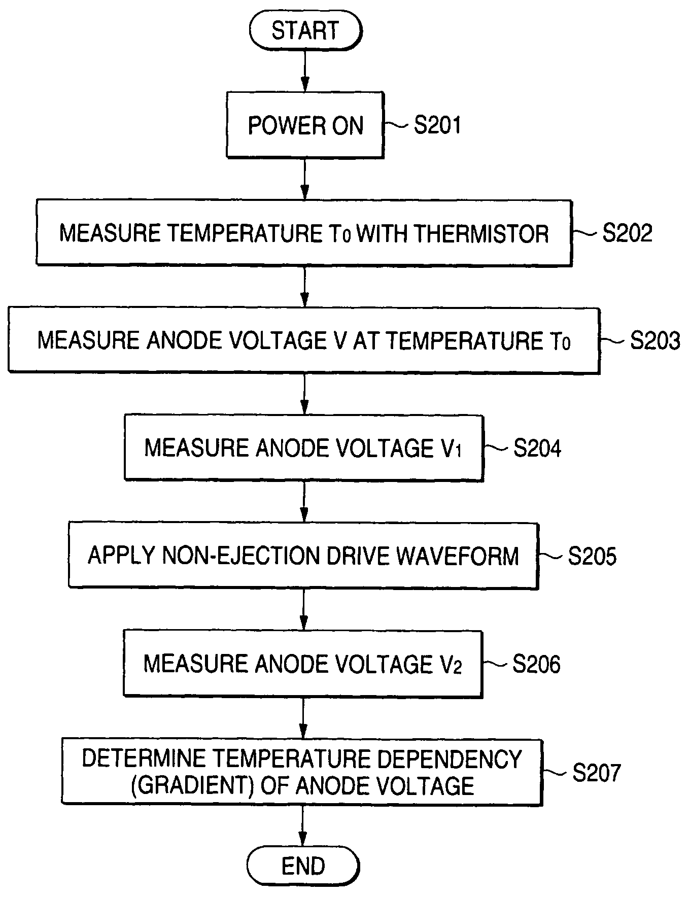
In short, the above-described temperature detecting method encounters difficulty in detecting temperatures accurately, because of individual differences in anode voltage at a certain temperature or individual differences in temperature coefficient of an anode voltage.
However, as a result of uninterrupted operation under extremely high load, heat dissipation capacity may become insufficient.
Moreover, in a state in which ink is not properly squirted for reasons of depletion of ink or clogging of nozzles, sufficient heat dissipation is not achieved.
If printing operation is continued in such a state, the temperatures of respective head driver ICs rise further, potentially resulting in thermal destruction of the respective head driver ICs.
The analog signals are susceptible to the influence of noise, thereby deteriorating the accuracy of detection.
Further, the number of input pins of the controller 4 increases, thereby resulting in a cost hike.
Accordingly, damage may be inflicted on the printer head.
In this way, when a temperature detecting circuit has become broken as a result of occurrence of a rupture in a signal line or a short-circuit in any one of circuits for detecting temperatures, the configuration shown in FIG. 6 encounters difficulty in immediately detecting the failure and taking a countermeasure, such as suspension of operation of a printer.

Method used


Image

  • Device and method for detecting temperature of head driver IC for ink jet printer
  • Device and method for detecting temperature of head driver IC for ink jet printer
  • Device and method for detecting temperature of head driver IC for ink jet printer

Examples


first embodiment

[0181]FIG. 7 shows the configuration of a head driver IC temperature detector according to the invention. An ink jet printer having the head driver IC temperature detector of the embodiment is a seven-color printer comprising: cyan (C), magenta (M), yellow (Y), black (K), light cyan (LC), light magenta (LM), and dark yellow (DY). The printer has a printer head comprising a total of eight rows of nozzles; namely, a row of cyan nozzles, a row of magenta nozzles, a row of yellow nozzles, two rows of black nozzles, a row of light-cyan nozzles, a row of light-magenta nozzles, and a row of dark-yellow nozzles.

[0182]The head driver IC temperature detector according to the embodiment is configured in a printer head 15 of the ink jet printer such that anode voltages of diodes provided in a plurality of head driver ICs 11a, 11b, 11c, 11d, 11e, 11f, 11g, and 11h (eight driver ICs) disposed for respective rows of nozzles are compared with the reference voltage. A result of comparison is digitiz...

second embodiment

[0213]FIG. 12 shows a head driver IC temperature detector of the invention. As shown in FIG. 12, a head driver IC temperature detector 30 is identical in construction with that shown in FIG. 7, and they differ from each other in only the following points.

[0214]More specifically, in the head driver IC temperature detector 30, the signals for temperature detection output from the respective head drivers ICs 11a through 11d are input to the controller 14 of the printer main unit 13 by way of the mutually-independent cables 12a, 12b, 12c, and 12d.

[0215]The head driver IC temperature detector 30 of such a configuration operates in the same manner as does the head drier IC temperature detector 10 shown in FIG. 1. The cables extending from the head driver ICs 11a through 11d are provided for the respective head driver ICs 11a through 11d. When a problem, such as a rupture, has arisen in any one of the cables 12a, 12b, 12c, and 12d, the temperature of only the head driver IC using the cabl...

third embodiment

[0216]FIG. 13 shows a head driver IC temperature detector of the invention. As shown in FIG. 13, a head driver IC temperature detector 40 is identical in configuration with the head driver IC temperature detector 10 shown in FIG. 12. They differ from each other only in the following points.

[0217]In the head driver IC temperature detector 40, outputs from the comparators 24 of the respective head driver ICs 11a through 11d are input directly to the controller 14 of the printer main unit 13, without involvement of the FET 25, by way of the mutually-independent cables 12a, 12b, 12c, and 12d.

[0218]The head driver IC temperature detector 40 of such a configuration operates in the same manner as does the head driver IC temperature detector 30 shown in FIG. 12. As a result of omission of the FET 25, a smaller number of components are required, and costs can be curtailed.

[0219]In the embodiments, each of the head driver IC temperature detectors 10, 30 is equipped with the four or eight hea...


PUM


Abstract

Each of a plurality of driver ICs, which drives an associated print head, includes an analog voltage provider, which provides an analog voltage which is inversely proportional to a temperature of the driver IC, a reference temperature provider, which provides a digital value corresponding to a reference temperature, a D / A converter, which converts the digital value into a corresponding analog value, and a comparator, which compares the analog voltage with the analog value and outputs a comparison signal indicating whether the analog voltage is higher than the analog value. A temperature detector determines whether the temperature of at least one of print heads is higher than the reference temperature in accordance with the comparison signal.

Description

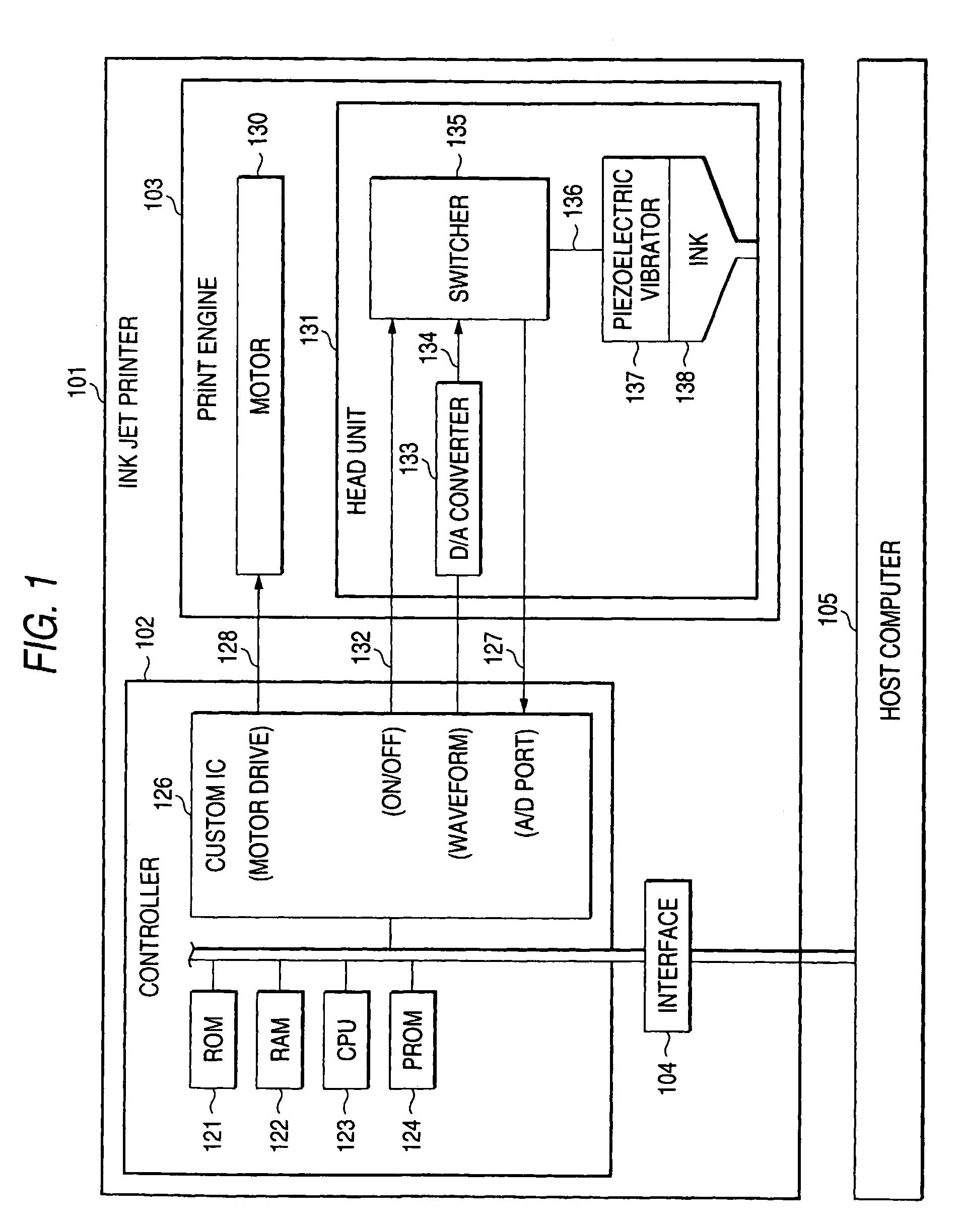
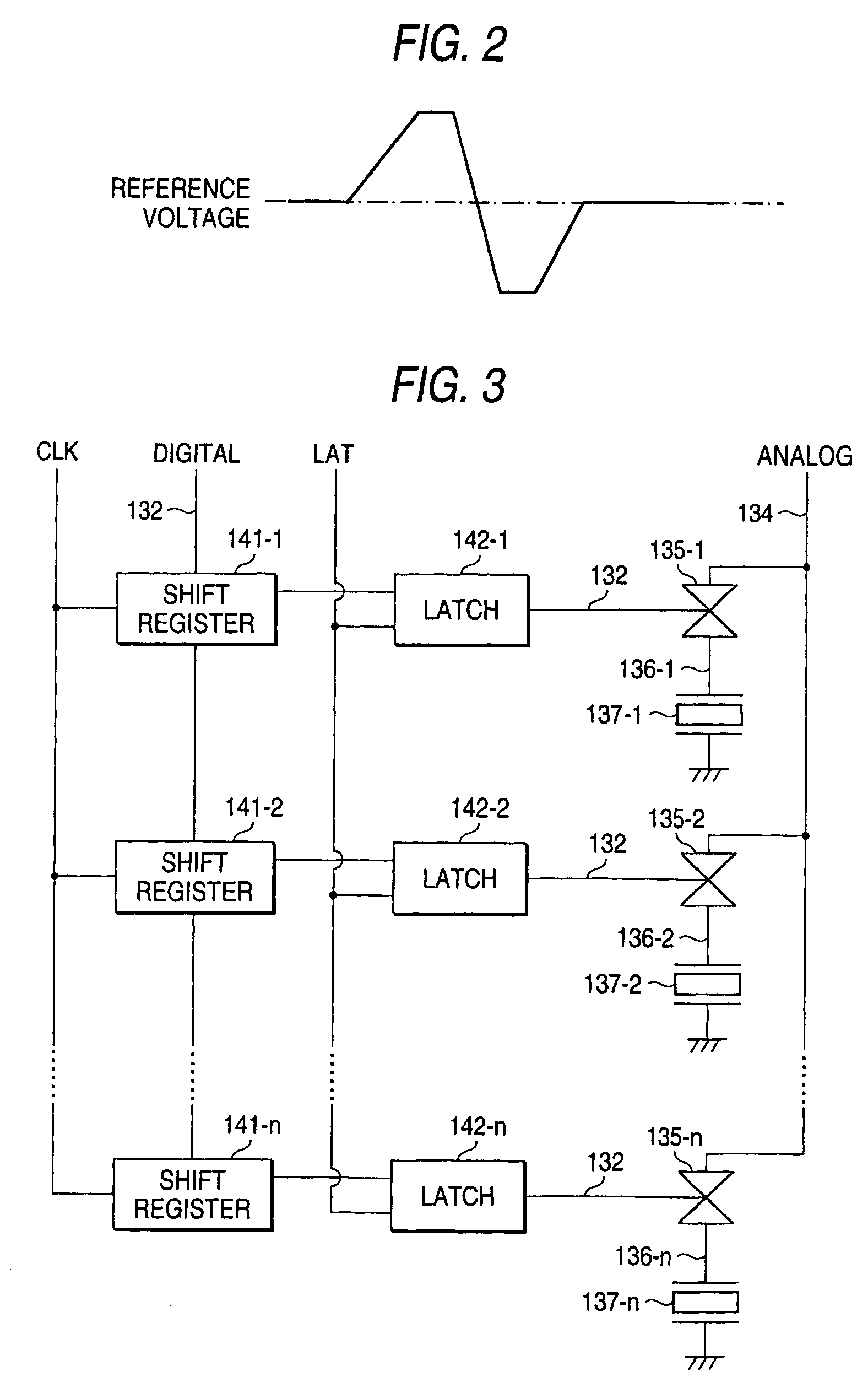
CROSS-REFERENCE TO RELATED APPLICATIONS[0001]This application is a Divisional Application of U.S. application Ser. No. 10 / 231,461 filed Aug. 30, 2002; the entire disclosure of which is incorporated herein by reference.BACKGROUND OF THE INVENTION[0002]The invention relates to a technique for detecting that head driver ICs of an ink jet printer have reached a predetermined temperature or higher.[0003]FIG. 1 shows the outline of hardware of an ink jet printer constituted by piezoelectric vibrators serving as elements for ejecting ink from nozzles. As shown in this figure, a controller 102 is a control board which is to be implemented in a printer and causes a print engine 103 to perform printing operation complying with data entered by way of an interface 104. A CPU (central processing unit) 123 executes a program stored in a ROM (read-only memory) 121, thereby controlling individual sections provided in the controller 102. A main bus of the controller 102 is connected to a RAM (random...

Claims


Application Information

Patent Timeline
Patent Type & Authority Patents(United States)
IPC IPC(8): B41J2/05B41J2/045
CPCB41J2/04541B41J2/04563B41J2/04581B41J2/04588
Inventor TAMURA, NOBORUNISHIHARA, YUICHI
Owner SEIKO EPSON CORP
Why Eureka
Try Eureka