Optical disc drive and optical pickup

a technology of optical disc drives and optical pickups, applied in the direction of data recording, instruments, disposition/mounting of heads, etc., can solve the problems of increasing thickness, reducing response characteristics, and inability to achieve appropriate wavefront correction for compensating aberrations

Inactive Publication Date: 2005-03-24
PANASONIC CORP
View PDF2 Cites 15 Cited by
  • Summary
  • Abstract
  • Description
  • Claims
  • Application Information

AI Technical Summary

Benefits of technology

In order to overcome the problems described above, preferred embodiments of the present invention provide an optical disc drive and an optical pickup that can make the wavefront corr

Problems solved by technology

Then, the wavefront correction for compensating for the aberrations cannot be achieved appropriately.
Nevertheless, the response characteristic should decrease due to the increase in the weight of the movable part, the actuator should have a complicated structure so as to get connected to the wavefront corrector appropriately, the optical pickup of that type should have an increased thickness, and various other secondary problems should arise.
The more necessary it is to make the wavefront corrector realize high-precision correction, process a multi-segment wavefront correction pattern and work in multiple different aberration modes properly, the more difficult it is to minimize the unwanted decrease in aberration correction ability while avoiding all those problems at the same time.
Firstly, the lens shift correcting mechanism disclosed in Japanese Laid-Open Publication No. 11-96577 tends to increase the overall size and co

Method used


Image

  • Optical disc drive and optical pickup
  • Optical disc drive and optical pickup
  • Optical disc drive and optical pickup

Examples


embodiment 1

Hereinafter, an apparatus according to a first specific preferred embodiment of the present invention will be described with reference to FIGS. 1 through 7. In the following preferred embodiment, the apparatus is implemented as an optical disc drive.

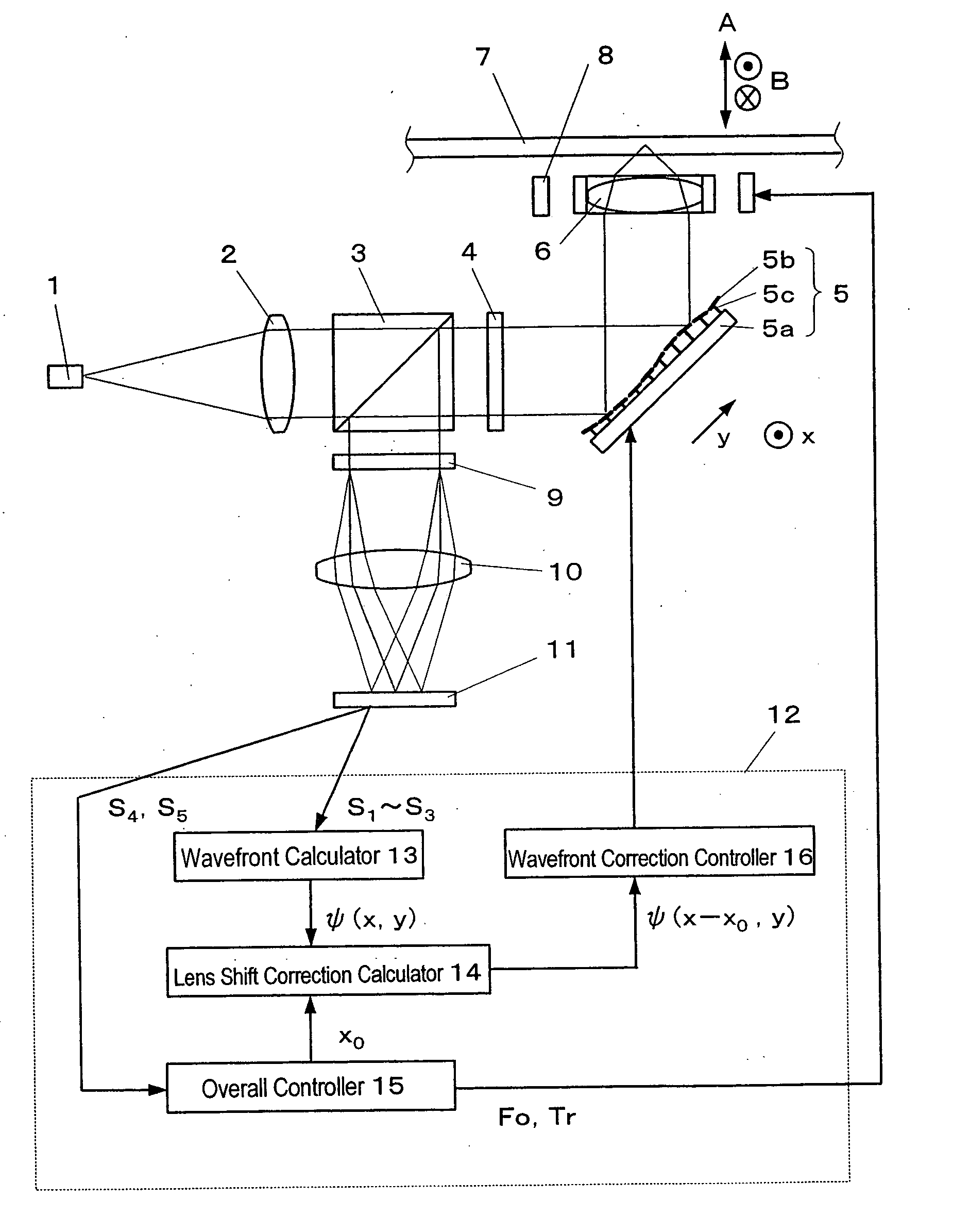
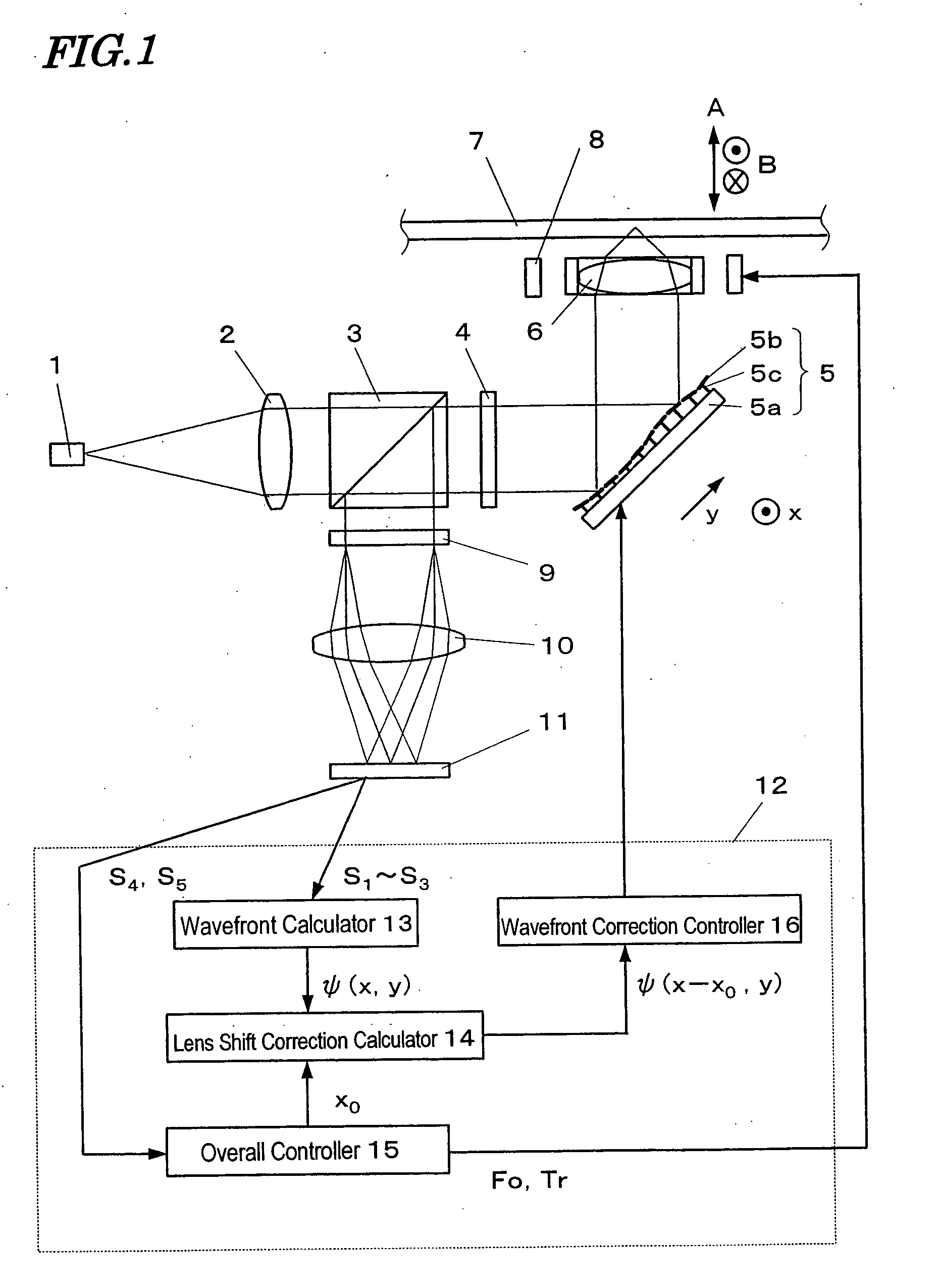
First, referring to FIG. 1, illustrated is a schematic configuration for an optical disc drive according to this first preferred embodiment. This optical disc drive is an apparatus for reading and / or writing data from / on a given medium (i.e., an optical disc in this case).

A light beam emitted from a light source 1 such as a GaN laser diode is transformed by a collimator lens 2 into an parallel light beam, which is then incident onto a polarization beam splitter 3. Only the P-polarized component of this light beam is transmitted through the polarization beam splitter 3, while the remaining S-polarized component is reflected from the polarization beam splitter 3 so as to enter a front light monitor (not shown). Thereafter, the transmi...

embodiment 2

Hereinafter, an optical disc drive according to a second specific preferred embodiment of the present invention will be described with reference to FIG. 8, which schematically illustrates a configuration for the optical disc drive of this second preferred embodiment.

In this second preferred embodiment, the light source 1, collimator lens 2, deformable mirror 5, objective lens 6, optical disc 7, objective lens actuator 8, photodetector 11, control section 12, wavefront calculator 13, lens shift correction calculator 14, overall controller 15 and wavefront correction controller 16 are identical with the counterparts that have already been described for the first preferred embodiment.

A light beam emitted from the light source 1 is transformed by the collimator lens 2 into an parallel light beam, which is then incident onto a half mirror 50. A portion of the light beam that has been transmitted through the half mirror 50 is incident onto a polarization beam splitter 51. Only the P-...

embodiment 3

Hereinafter, an optical disc drive according to a third specific preferred embodiment of the present invention will be described with reference to FIG. 10, which schematically illustrates a configuration for the optical disc drive of this third preferred embodiment.

In this third preferred embodiment, the structures and operations of the light source 1, collimator lens 2, polarization beam splitter 3, quarter-wave plate 4, deformable mirror 5, objective lens 6, optical disc 7, objective lens actuator 8, lens 10, lens shift correction calculator 14, and wavefront correction controller 16 are identical with those of the counterparts that have already been described for the first preferred embodiment.

The light beam that has returned from the optical disc 7 to the polarization beam splitter 3 is reflected from the polarization beam splitter 3, passed through the lens 10, given astigmatism by a cylindrical lens 20 and then incident onto a photodetector 11b. The photodetector 11b incl...


PUM


Abstract

An apparatus for reading and/or writing data from/on a medium with a light beam includes: a light source for generating the light beam; an objective lens for focusing the beam onto the medium; a lens shift sensor for sensing how much the optical axis of the objective lens has shifted from that of the beam; a wavefront corrector, in which correcting elements are arranged as a two-dimensional array so as to locally correct the wavefront of the beam and to be driven independently of each other; a wavefront calculator for finding correlation between each coordinate on a cross section of the beam and the wavefront phase of the beam; a lens shift correction calculator for modifying the coordinate-wavefront phase correlation according to the output of the lens shift sensor; and a controller for controlling the wavefront corrector in accordance with the output of the lens shift correction calculator.

Description

BACKGROUND OF THE INVENTION 1. Field of the Invention The present invention generally relates to an apparatus for optically reading and / or writing information (or data) from / on a given medium, and more particularly relates to an optical disc drive and an optical pickup each including a wavefront corrector for controlling the wavefront of a light beam. 2. Description of the Related Art Generally speaking, in an apparatus such as an optical disc drive for reading and / or writing information optically from / on a storage medium (e.g., an optical disc), a wavefront corrector such as a liquid crystal element or a deformable mirror is often provided along the optical path of an incoming light beam in order to compensate for aberrations caused by variations in the tilt and base material thickness (i.e., the depth of the data storage layer) of the optical disc. In this case, it is important to minimize the decrease in aberration correction ability due to the shift of the optical axis of an...

Claims


Application Information

Patent Timeline
IPC IPC(8): G11B7/00G11B7/09G11B7/095G11B7/135
CPCG11B7/1362G11B7/13927G11B7/1369
Inventor MUSHIKA, YOSHIHIROKAJINO, OSAMU
Owner PANASONIC CORP
Why Eureka
Try Eureka