Line-marking tool for numerical control milling machine and line-marking method thereof

A CNC milling machine and engraving technology, which is applied to the engraving tool and its engraving field for CNC milling machines, can solve the problems of lack of CNC milling machine engraving accuracy, low processing efficiency, etc., achieve uniform force, improve processing efficiency, Avoid the effect of overstressing

Inactive Publication Date: 2012-02-22
HARBIN TURBINE
View PDF12 Cites 8 Cited by
  • Summary
  • Abstract
  • Description
  • Claims
  • Application Information

AI Technical Summary

Problems solved by technology

[0003] The present invention solves the problem that there is no dedicated engraving tool for CNC milling machines and the existing method of engraving reference lines has low engraving precision and low processing efficiency, and further provides a engraving tool and its engraving method for numerical control milling machines

Method used


Image

  • Line-marking tool for numerical control milling machine and line-marking method thereof
  • Line-marking tool for numerical control milling machine and line-marking method thereof

Examples


specific Embodiment approach 1

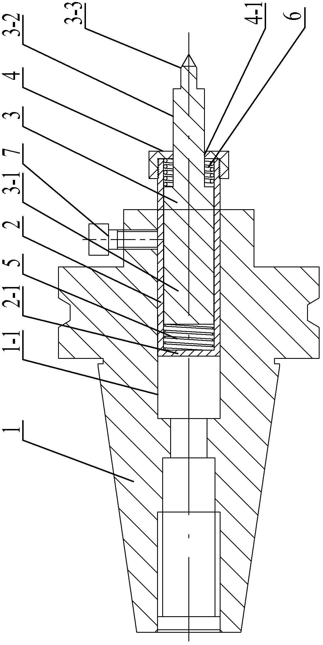
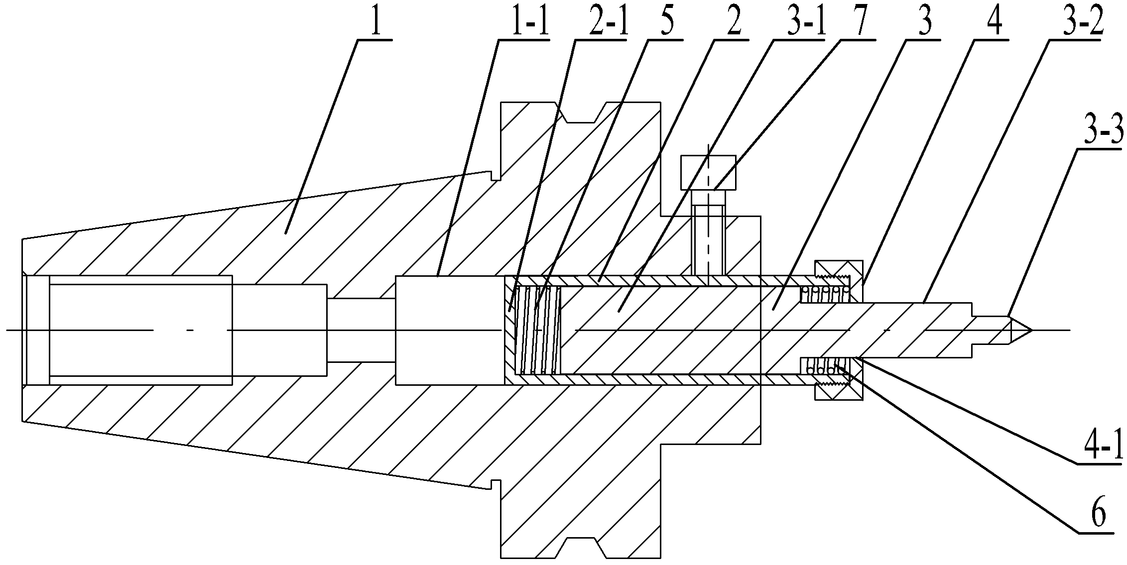
[0018] Specific implementation mode one: as figure 1 As shown, the marking tool for the CNC milling machine of the present embodiment includes a cutter bar 1, a sleeve 2, a marking needle 3, an end cover 4, a first spring 5, a second spring 6 and a locking screw 7, the The tool bar 1 is processed with a stepped through hole 1-1 along the axial direction, and one end of the sleeve 2 is provided with a bottom 2-1, and the bottom end of the sleeve 2 is inserted into the stepped through hole 1-1, and the sleeve 2 passes through the The locking screw 7 is affixed to the cutter bar 1, the first spring 5 is located in the sleeve 2 and one end of the first spring 5 is in contact with the bottom of the cylinder 2-1, and the engraving needle 3 is formed by a large cylindrical section 3-1 , small cylindrical section 3-2 and engraved line head 3-3, the large cylindrical section 3-1, small cylindrical section 3-2 and engraved line head 3-3 are fixed in sequence as one, and the large cylind...

specific Embodiment approach 2

[0019] Specific implementation mode two: as figure 1 As shown, the end cap 4 in this embodiment is screwed to the open end of the sleeve 2 . Designed in this way, it is connected by thread, so it is easy to disassemble. Other components and connections are the same as those in the first embodiment.

specific Embodiment approach 3

[0020] Specific Embodiment Three: The engraving head 3-3 in this embodiment is a cemented carbide engraving head. With such a design, the cemented carbide engraving head has high hardness and wear resistance, and has a long service life. Other compositions and connections are the same as those in Embodiment 1 or 2.


PUM


Abstract

The invention provides a line-marking tool for a numerical control milling machine and a line-marking method thereof and relates to a line-marking tool and a line-marking method. The invention aims to solve the problems that no special line-marking tool for the numerical control milling machine exists at present and a traditional datum line marking method is low in line-marking precision and processing efficiency. The bottom of a sleeve is plugged in a stepped through hole; a first spring is located in the sleeve; one end of the first spring is in contact with the bottom of the sleeve; a big cylindrical section, a small cylindrical section and a line-marking head are fixedly and integrally connected in turn; the other end of the first spring is in contact with the big cylindrical section; a second spring passes through the small cylindrical section; one end of the second spring is in contact with the big cylindrical section; an end cover passes through the small cylindrical section and is fixedly mounted at an opening end of the sleeve; and the other end of the second spring is in contact with the end cover. The line-marking method comprises the following steps: clamping the line-marking tool on a spindle of a machine tool; setting a program of the numerical control milling machine according to a required line-marking track; and marking lines on a workpiece by the line-marking tool according to the set program of the numerical control milling machine. The line-marking tool and the line-marking method are used for marking the lines on a special tool.

Description

technical field [0001] The invention relates to a marking tool for a numerically controlled milling machine and a marking method thereof. Background technique [0002] Many special tooling in the factory, such as drilling jigs, marking boards, etc., need to engrave reference lines on the drilling jigs and marking boards to ensure the accuracy of the tooling. Currently, there is no special engraving tool for CNC milling machines. The existing engraving datums The line method adopts manual scribing and engraving, which leads to low engraving accuracy, and the engraving accuracy is about 0.5mm. Especially when engraving on inclined or curved surfaces, the accuracy is difficult to guarantee and the processing efficiency is low. Contents of the invention [0003] The present invention solves the problem that there is no dedicated engraving tool for CNC milling machines and the existing method of engraving reference lines has low engraving precision and low processing efficiency...

Claims


Application Information

Patent Timeline
Patent Type & Authority Applications(China)
IPC IPC(8): B25H7/04
Inventor 叶云青孙忠鹏杨金胜魏成双
Owner HARBIN TURBINE
Why Eureka
Try Eureka