Pneumatic mechanical claw for picking up bearing
A technology of manipulator claws and bearings, applied in the field of manipulators, can solve problems such as high cost, complex manipulator structure, and difficulty in manufacturing.
- Summary
- Abstract
- Description
- Claims
- Application Information
AI Technical Summary
Problems solved by technology
Method used
Image


Examples
Embodiment Construction
[0010] The present invention will be further described below in conjunction with the accompanying drawings and embodiments.
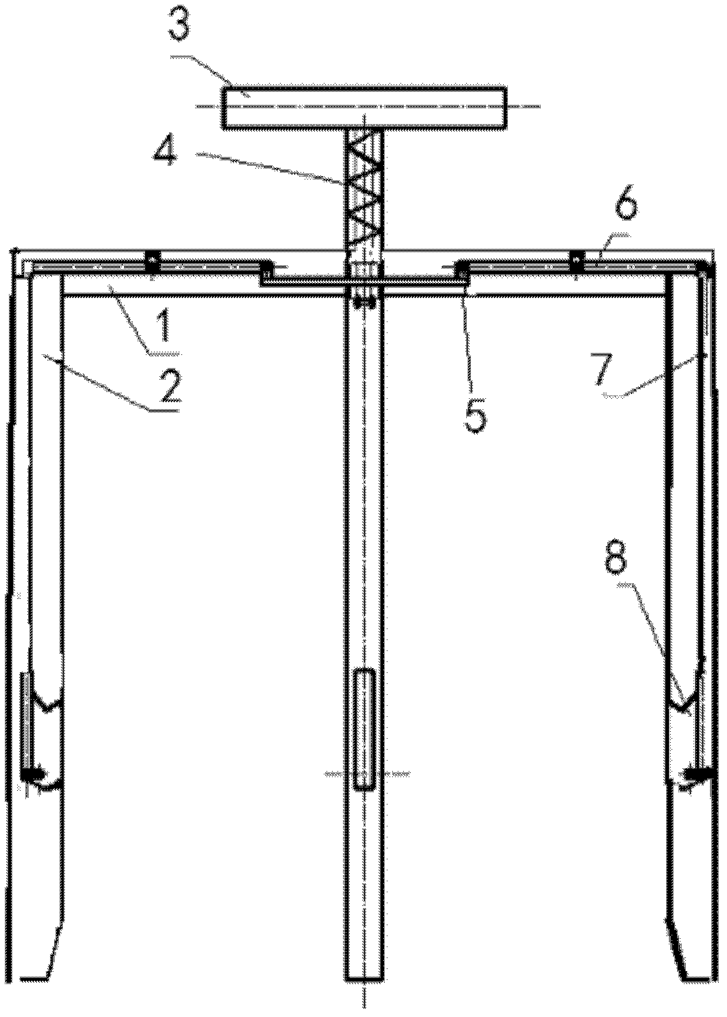
[0011] Pneumatic grippers for picking bearings, e.g. figure 1 As shown, it includes a triangular upper cover 1, three fixed arms 2, a movable handle 3, a lever connecting body 5, a lever 6, a connecting rod 7, and a movable claw 8. The movable handle 3 is provided with a spring 4, and the upper cover 1 is connected to the fixed arm 2, the movable handle 3 is connected to the lever 6, the lever connecting body 5 is connected to the lever 6, the lever 6 is connected to the connecting rod 7, and the connecting rod 7 is connected to the movable claw 8. link, the lever 7 is movably linked with the triangular upper cover 1, and the movable claw 8 is movably linked with the fixed arm 2. The movable handle 3 and the lever 6 are fastened by bolts.
[0012] Although the specific implementation of the invention has been described above in conjunction with the ac...
PUM
 Abstract
Description
Claims
Application Information
 - R&D
- Intellectual Property
- Life Sciences
- Materials
- Tech Scout
- Unparalleled Data Quality
- Higher Quality Content
- 60% Fewer Hallucinations
Browse by: Latest US Patents, China's latest patents, Technical Efficacy Thesaurus, Application Domain, Technology Topic, Popular Technical Reports.
© 2025 PatSnap. All rights reserved.Legal|Privacy policy|Modern Slavery Act Transparency Statement|Sitemap|About US| Contact US: help@patsnap.com