

Two-control multi-constant-pressure water supply equipment control system and control method thereof
A technology of equipment control and constant pressure water supply, applied in the water supply pipeline system, water supply device, water supply main pipeline, etc., can solve the problems such as the inability to achieve a smooth transition of the water supply pressure, reduce the operating efficiency of the pump set, and avoid the impact of the water supply pressure. Water hammer effect, improved service life, stable water supply pressure
- Summary
- Abstract
- Description
- Claims
- Application Information
AI Technical Summary
Problems solved by technology
Method used
Image

Examples
Embodiment
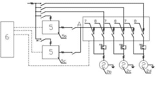
[0062] see figure 2 (FR1, FR2, and FR3 in the figure are thermal relay protection devices), taking the start and stop process of three water pumps as an example:
[0063] When the system starts to run, turn on the inverter 5 of No. 5b, turn off the inverter 5 of No. 5c, and at the same time, turn the water pump 2 of No. 8 is disconnected) connected to the system, and the other pumps 2 are not connected; within the pressure range that one pump 2 can provide, the frequency converter 5 of No. 5b drives the pump 2 of No. No. 5b frequency converter 5 dynamically outputs control signals;
[0064] As the water consumption rises, the control unit 6, according to the preset threshold (reaching the threshold will be delayed for a certain period of time), before the No. 2b water pump 2 reaches full load operation (at this time, the speed of the No. volume), connect No. 2c water pump 2 to the system in frequency conversion mode (the first contactor 7 on No. 2 to complete the soft star...
PUM
 Abstract
Description
Claims
Application Information