Overall input decoupling device for multi-rotor unmanned aerial vehicle and control system with device

A multi-rotor unmanned aerial vehicle, input decoupling technology, applied in the field of control system, multi-rotor unmanned aerial vehicle global input decoupling device, can solve the problems of complex control, difficult degree of freedom dynamic decoupling, etc., to reduce the complexity Effect

Active Publication Date: 2013-06-19
CHANGCHUN INST OF OPTICS FINE MECHANICS & PHYSICS CHINESE ACAD OF SCI
View PDF2 Cites 0 Cited by
  • Summary
  • Abstract
  • Description
  • Claims
  • Application Information

AI Technical Summary

Problems solved by technology

The current multi-rotor UAV control system does not have a general method for decoupling. The change of each state quantity is affected by multiple rotor speeds, and the change of any rotor speed will also change multiple state quantities. , the control is complicated, and it is not easy to realize the dynamic decoupling of each degree of freedom, so as to realize the independent control of each degree of freedom (position and attitude)

Method used


Image

  • Overall input decoupling device for multi-rotor unmanned aerial vehicle and control system with device
  • Overall input decoupling device for multi-rotor unmanned aerial vehicle and control system with device
  • Overall input decoupling device for multi-rotor unmanned aerial vehicle and control system with device

Examples


Embodiment 1

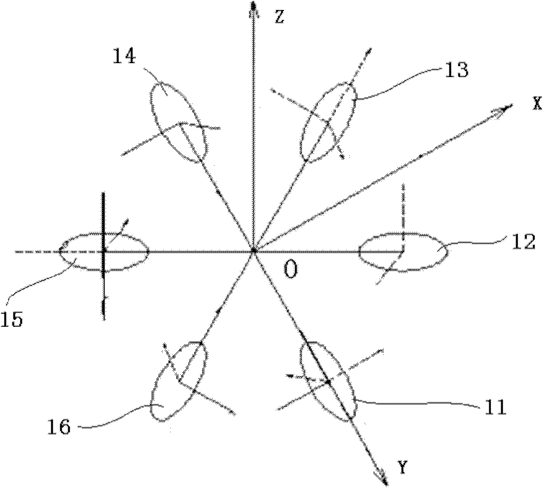
[0040] Such as image 3 As shown, the body of the full-drive six-rotor UAV is equipped with six connecting rods, which are evenly distributed around the body. The outer ends of the six connecting rods are respectively connected to No. 1, No. 2, ..., and No. ..., 16. Each rotor can be driven by a motor or an oil engine. The x and y axes of the body coordinate system of the rotor drone are located in the plane where the six connecting rods are located and are perpendicular to each other. The z axis passes through the center of mass of the drone and is perpendicular to The plane where the six connecting rods are located. The rotation planes of the six rotors form six inclinations with the xoy plane of the body coordinate system, and the rotation planes of each rotor are equal to the rotation planes of the third rotor separated by two rotors; the rotation planes of each rotor are the same as the adjacent rotors The inclination angle between the rotation plane of the first rotor 1...

Embodiment 2

[0068] Such as Figure 5 As shown, the body of the underactuated six-rotor UAV is provided with three connecting rods, which are evenly distributed around the body. The outer end of each connecting rod is connected to the upper and lower rotors. At the outer end of the bar, No. 3 and No. 4 rotors 23 and 24 are connected to the outer ends of the same connecting rod, and No. 5 and No. 6 rotors 25 and 26 are connected to the outer ends of the same connecting rod. Each rotor can be driven by a motor or an oil engine.

[0069] The relationship between the virtual control quantity of the degree of freedom of the underactuated hexacopter UAV and the rotor speed is as follows:

[0070] U 21 U 22 U 23 ...


PUM


Abstract

The invention relates to an overall input decoupling device for a multi-rotor unmanned aerial vehicle. The device comprises a coefficient matrix Mco storage module, a structure matrix Mrel storage module and a leading rotor speed operation module, wherein a coefficient matrix Mco and a structure matrix Mrel are multiplied and inversed to obtain a module of an inverse matrix (Mco.Mrel)<-1>. By non-linear decoupling mapping, the input decoupling of the multi-rotor unmanned aerial vehicle is realized under the condition of unknown models, so that the multi-rotor unmanned aerial vehicle, namely amulti-input multi-output system is decoupled into a plurality of single-input single-output subsystems, and each degree of freedom is only influenced by one subsystem loop. Therefore, the degree of freedom (positions and postures) is independently controlled, the control complexity of the system is reduced, the system is easy to control, and the device does not depend on a mathematical model of an object, has a wide application range and is suitable for multi-rotor unmanned aerial vehicles with arbitrary structures.

Description

technical field [0001] The invention belongs to the field of control of multi-rotor unmanned aerial vehicles, and relates to a multi-rotor unmanned aerial vehicle global input decoupling device and a control system including the device. Background technique [0002] The hexacopter UAV is different from other rotor UAVs such as helicopters and quadrotor UAVs. By changing the organizational form of the six rotors, the system can present different working modes of underactuation or full actuation. Compared with the general multi-rotor UAV, which needs to control the change of attitude angle and then control the horizontal movement, the full-drive six-rotor UAV adopts a unique structural configuration, which can directly control the horizontal movement. The UAV is highly maneuverable and can Realize special functions such as fast forward flight, hovering and forward flight with any attitude. The underactuated six-rotor UAV also has research value because of its relatively simpl...

Claims


Application Information

Patent Timeline
Patent Type & Authority Patents(China)
IPC IPC(8): G05D1/08G05D1/10
Inventor 白越侯至丞宫勋高庆嘉孙强续志军
Owner CHANGCHUN INST OF OPTICS FINE MECHANICS & PHYSICS CHINESE ACAD OF SCI
Why Eureka
Try Eureka