Signal generation apparatus and method thereof for controlling output frequency and output characteristic of chaotic signal
A technology of signal generation device and output frequency, which is applied in the direction of safety communication device, transmission system, digital transmission system, etc., can solve the problem of not being able to change the output frequency and characteristics of the chaotic system, so as to avoid copying and tracking, and control is convenient, fast and convenient The effect of frequency control
- Summary
- Abstract
- Description
- Claims
- Application Information
AI Technical Summary
Problems solved by technology
Method used
Image
Examples
Embodiment 1
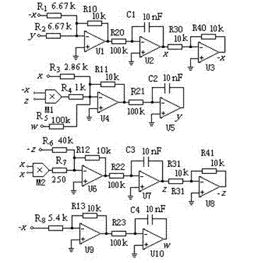
[0053] At this time, the circuit diagram of the system is as follows figure 2 , as can be seen from the figure, the simulated chaotic circuit includes channel circuit I, channel circuit II, channel circuit III and channel circuit IV;
[0054] Channel circuit I, channel circuit II, channel circuit III and channel circuit IV are respectively used to realize the first, second, third and fourth functions in the mathematical model;
[0055] Channel circuit I includes resistors R1, R2, R10, R20, R30, and R40, capacitor C1, and inverting amplifiers U1, U2, and U3. The non-inverting terminals of U1, U2, and U3 are all grounded, and one end of the resistors R1 and R2 They are respectively used as the input ends of the state variables, and the other end is connected in parallel to the inverting end of U1. The resistor R10 is connected between the inverting end and the output end of U1, and the resistor R20 is connected between the output end of U1 and the inverting end of U2. Between ...
Embodiment 2
[0062] Change the output frequency of the chaotic system:
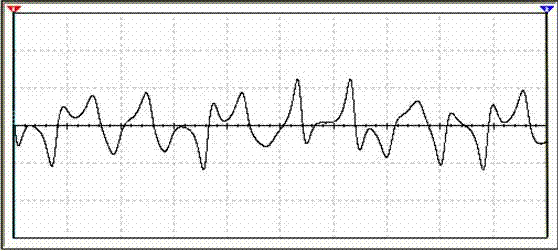
[0063] When replacing the first integral capacitor of the system with C1=5nf, the circuit diagram of the new system is as follows Figure 5 As shown, the system output is as Figure 6 shown. It can be seen from the figure that the up and down fluctuations of the chaotic signal are more frequent.
Embodiment 3
[0065] Change the output characteristics of the chaotic system:
[0066] When putting the first parameter of the system in the controller R 1 replace R 1 =4K, the circuit diagram of the new system is as follows Figure 7 As shown, the system output is as Figure 8 shown. It can be seen from the figure that the system produces different chaotic attractors.
[0067] In fact, capacitors C1, C2, C3, C4, R20, R21, R22 and R23 can be combined into a system output frequency changing module, which is equivalent to the function of the output frequency controller and can facilitate the modification of the system output frequency; The resistors R1 , R2 , R3 , R4 , R5 , R6 , R7 and R8 can be combined into a chaotic characteristic changing module, which is equivalent to the function of the output characteristic controller and can facilitate modification of the chaotic characteristic of the system. Through the way of module control, multiple output signals can be obtained with the same...
PUM
 Abstract
Description
Claims
Application Information
 - R&D
- Intellectual Property
- Life Sciences
- Materials
- Tech Scout
- Unparalleled Data Quality
- Higher Quality Content
- 60% Fewer Hallucinations
Browse by: Latest US Patents, China's latest patents, Technical Efficacy Thesaurus, Application Domain, Technology Topic, Popular Technical Reports.
© 2025 PatSnap. All rights reserved.Legal|Privacy policy|Modern Slavery Act Transparency Statement|Sitemap|About US| Contact US: help@patsnap.com


