Pipe connecting connector

A connector and pipe connection technology, used in couplings, mechanical equipment, etc., can solve the problems of poor operability and large operating force, and achieve the effect of good operability

Inactive Publication Date: 2014-03-12
NIFCO INC
View PDF8 Cites 0 Cited by
  • Summary
  • Abstract
  • Description
  • Claims
  • Application Information

AI Technical Summary

Problems solved by technology

[0006] However, the above-mentioned conventional connector has the following problems: when the connection is released, the arm is expanded radially outward so that the hook passes over the rib, so the user needs a large operating force, and the operability is poor.

Method used


Image

  • Pipe connecting connector
  • Pipe connecting connector
  • Pipe connecting connector

Examples


Embodiment Construction

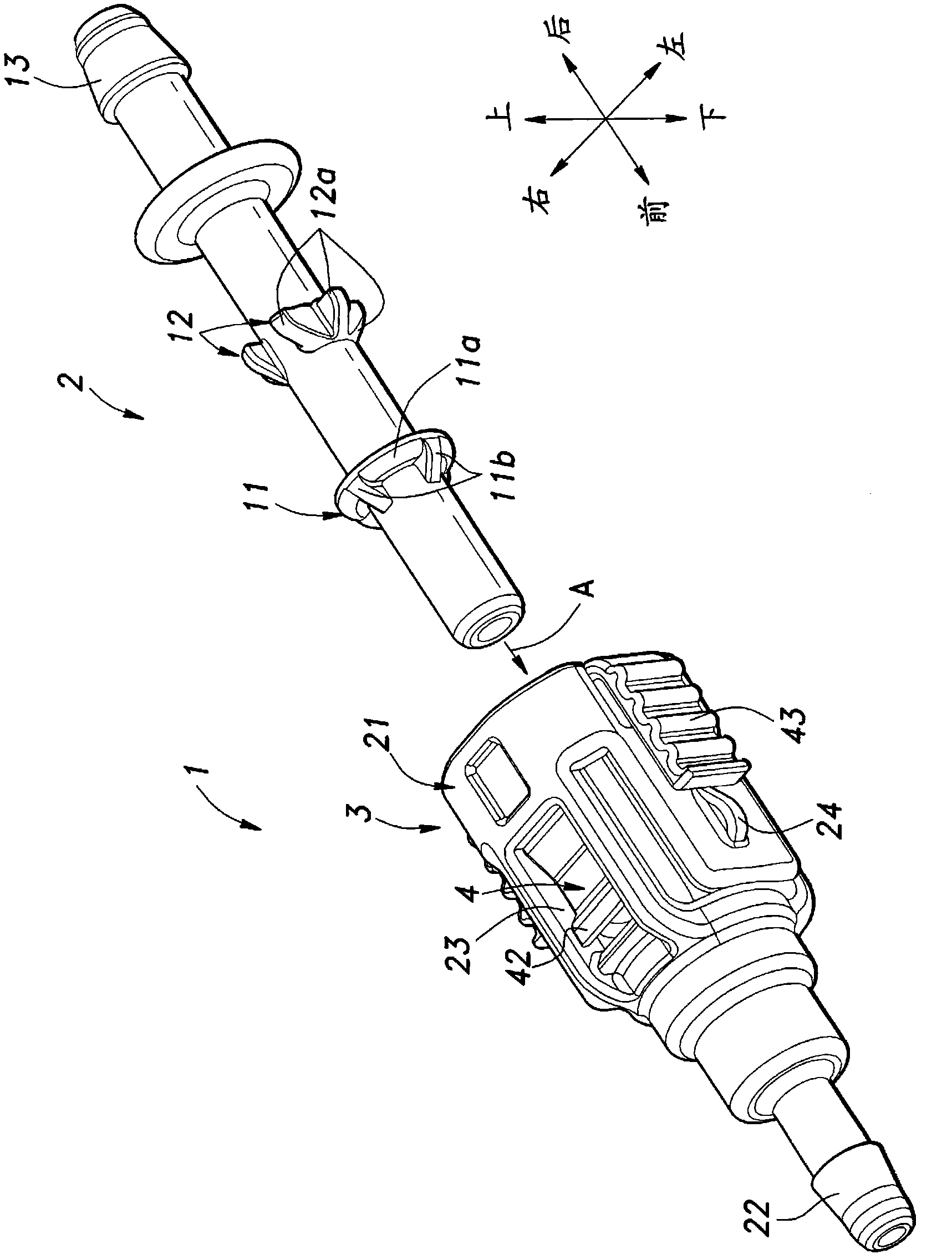
[0034] Refer below Figure 1 to Figure 10 The pipe connection connector according to the embodiment of the present invention will be described. In the following, the terms "upper", "lower", "front", "rear", "left" and "right" denoting direction are used according to figure 1 The direction shown is OK. For example, tube 2 relative to figure 1 The shown insertion direction (arrow A direction) of the connector 1 along the axis corresponds to "front", and the opposite direction corresponds to "rear".

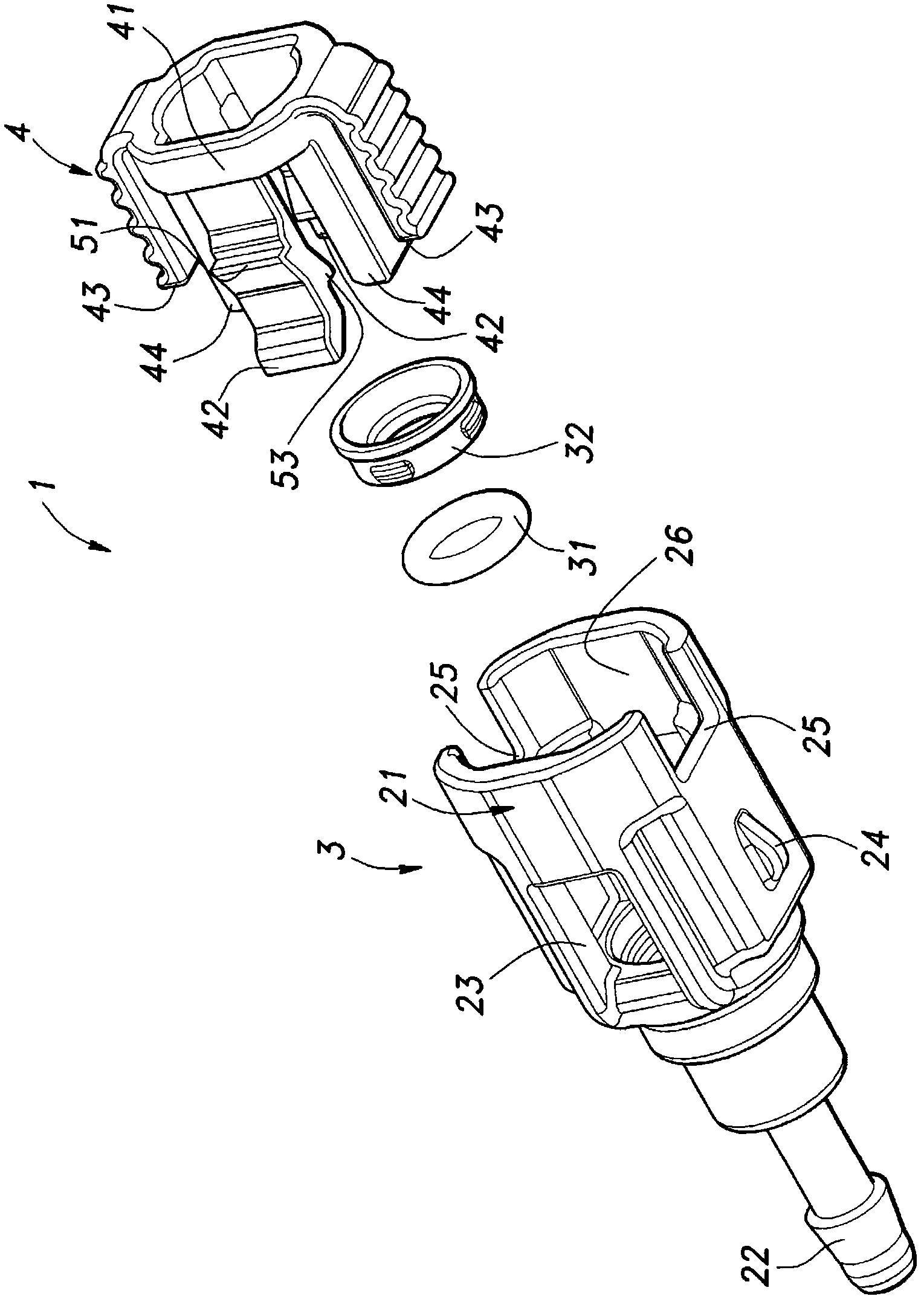
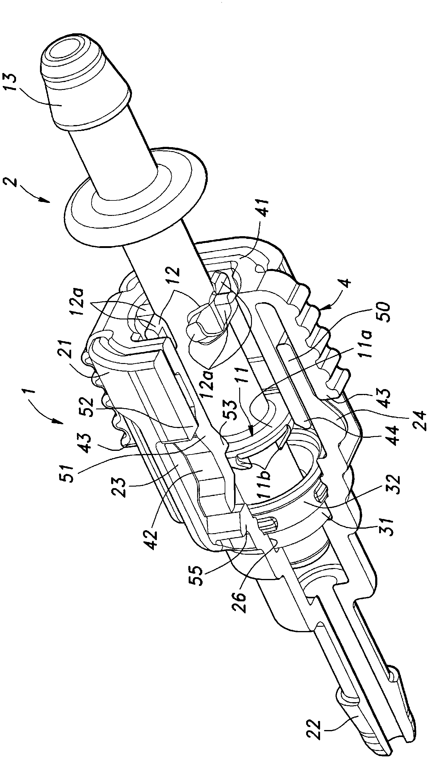
[0035] like Figure 1 to Figure 4 As shown, the connector for pipe connection (hereinafter referred to as the connector) 1 is a component used to connect the pipe 2 for fluid delivery to the connection object (not shown), and the connector mainly includes: inserting the pipe 2 and a locking member 4 that is slidably held on the connector body 3 and that fixes the tube 2 according to the sliding action.

[0036] like figure 1 As shown, the tube 2 is equipped with: a front flang...


PUM


Abstract

A connector for pipe connection provided to stably hold a state of connection of a pipe, and to improve operability by a user when disconnecting the pipe. The connector (1) for pipe connection has a connector body (3) in which a pipe (2) is inserted and removed; a lock member (4) held slidably in the connector body for fastening the pipe by locking pieces (42) and (42); and operating pieces (43) and (43) provided for operating to slide the lock member; and is configured such that the locking piece is elastically deformed from a fastened state in which the pipe is fastened to a released state in which the pipe is released by being pressed against a pressing part (55) formed on the connector body when the lock member is operated to slide.

Description

technical field [0001] The present invention relates to a pipe connection connector for connecting a pipe to a connection object. Background technique [0002] Conventionally, there has been known a connector for connecting a plastic hose to a pipe provided in a radiator housing of an automobile, the connector having: a cylindrical sleeve for connecting the hose; The barrel sleeve is movably mounted between a connection position and a connection release position, and is provided with a stopper for locking an arm of the hose at the connection position (see Patent Document 1). [0003] In this connector, the arm of the blocking device is formed to be elastically bent in the radial direction, and when the blocking device is located at the connection position, it fits into the radially inner recess of the hook provided at one end side of the arm. The rib protrudingly provided on the outer peripheral surface of the hose, and the radially outer inclined surface of the hook part a...

Claims


Application Information

Patent Timeline
Patent Type & Authority Patents(China)
IPC IPC(8): F16L37/12
CPCF16L37/0982F16L37/0987F16L37/12F16L37/113F16L37/098
Inventor 中村高章
Owner NIFCO INC
Why Eureka
Try Eureka