Mounting table structure and treatment device

A technology of processing device and mounting table, which is applied to electric heating device, gaseous chemical plating, coating, etc., can solve the problems of reduced surface uniformity of wafer temperature and inability to effectively correspond to it, etc.

Inactive Publication Date: 2012-02-22
TOKYO ELECTRON LTD
View PDF8 Cites 18 Cited by
  • Summary
  • Abstract
  • Description
  • Claims
  • Application Information

AI Technical Summary

Problems solved by technology

In such a situation, the peripheral portion of the wafer W is easily adversely affected by local heat from the mounting portion of the gate valve 12 and the mounting portion of the observation window 14 having different temperatures.
[0009] However, as described above, the resistance heater 24B in the outer peripheral region that controls the temperature of the peripheral portion of the wafer W can only control the overall temperature.
Therefore, when the peripheral portion of the crystal piece is affected by heat, it cannot effectively cope with it, so there is a problem that the in-plane uniformity of the wafer temperature decreases.

Method used


Image

  • Mounting table structure and treatment device
  • Mounting table structure and treatment device
  • Mounting table structure and treatment device

Examples


Embodiment Construction

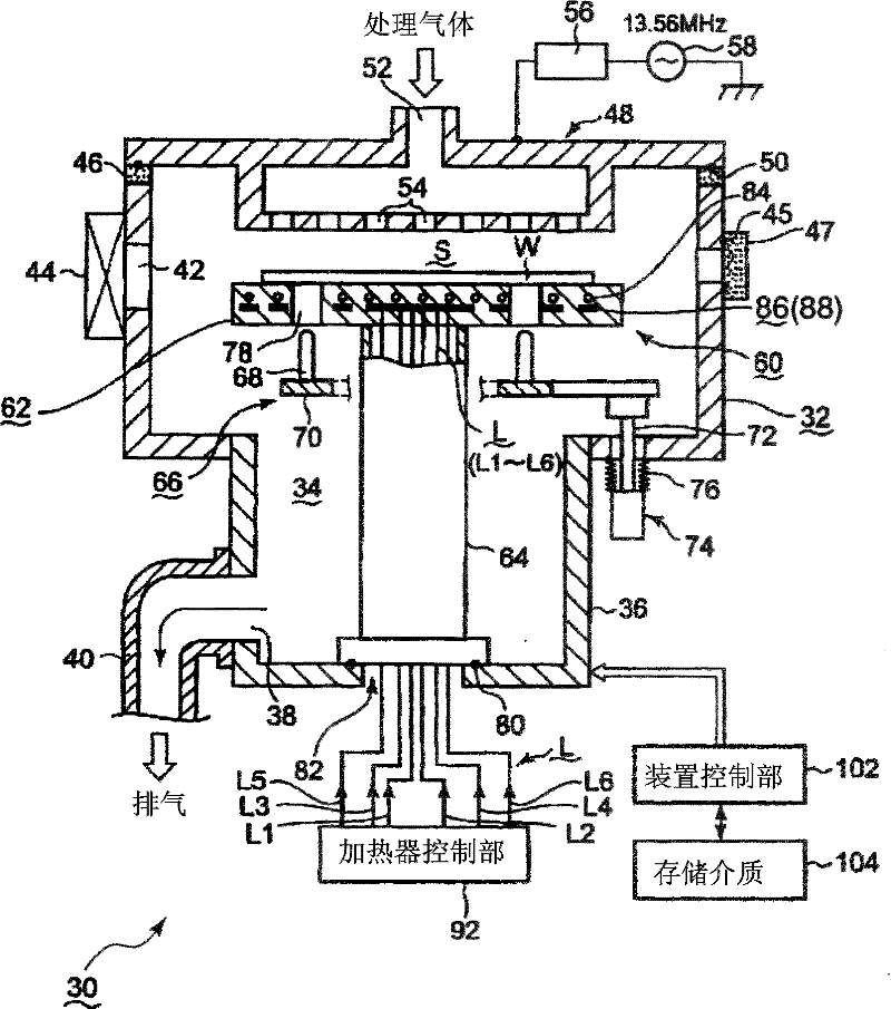
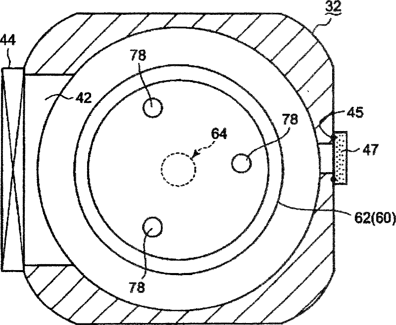
[0030] Hereinafter, one embodiment of the mounting table structure and processing apparatus of the present invention will be described in detail based on the drawings. figure 1 It is a block diagram showing a processing device having a mounting table structure of the present invention, figure 2 is a schematic cross-sectional view showing the inside of the processing container, image 3 It is a plan view showing the arrangement of resistance heaters of the heating mechanism.

[0031] Here, as the processing apparatus of the present invention, a parallel plate type plasma processing apparatus will be described as an example. like figure 1 As shown, a parallel plate type plasma processing apparatus 30 has a processing container 32 formed in a cylindrical shape, for example, from an aluminum alloy or the like. In the central part of the bottom of the processing container 32, an exhaust space 34 is further recessed downward and convexly formed by partitioning off a bottomed c...


PUM


Abstract

Provided is a mounting table structure (60) on which an object (W) to be treated is mounted in order to be heat-treated in a treatment container and which heats the mounted object to be treated. Outermost peripheral feed lines (L1-L4) are connected to a plurality of positions different in the circumferential direction of an outermost peripheral resistance heating heater (100) for heating an outermost peripheral heating zone (96) of a mounting table body (62), thereby dividing the outermost peripheral resistance heating heater (100) into a plurality of heater sections (100A-100D). A heater control unit (92) can individually control electrical states (for example, voltage application states, zero potential states, and floating states) of the respective outermost peripheral feed lines. The power supply state of each of the heater sections can be changed by a simple configuration.

Description

technical field [0001] The present invention relates to a processing device for performing heat treatment such as plasma processing or film forming processing on a target object such as a semiconductor wafer, and to a mounting table structure used in the processing device. Background technique [0002] In general, in order to manufacture semiconductor devices such as ICs (Integrated Circuits), various processes such as film formation, etching, heat treatment, and modification are repeatedly performed on a target object such as a semiconductor wafer with or without plasma. , to manufacture target circuit devices, etc. [0003] Taking a monolithic processing device that performs heat treatment on each piece of a semiconductor wafer as an example, a mounting table structure with a built-in resistance heater is provided in a processing container that can be evacuated, and the semiconductor wafer is placed on the mounting table. Various heat treatments are performed on the wafer...

Claims


Application Information

Patent Timeline
Patent Type & Authority Applications(China)
IPC IPC(8): H01L21/02C23C16/46H01L21/3065H01L21/31H01L21/324H01L21/683H05B3/20
CPCC23C16/4586C23C16/46H01J37/32091H01J2237/2001H01L21/67103H01L21/67109H01L21/67248H05B3/22H05B2203/037
Inventor 小松智仁
Owner TOKYO ELECTRON LTD
Why Eureka
Try Eureka