Battery module

A technology of battery modules and single cells, which is applied in the direction of secondary batteries, battery pack components, battery temperature control, etc., can solve the problem of not being able to firmly maintain single cells, and achieve the effect of suppressing temperature rise

Inactive Publication Date: 2012-02-22
PANASONIC CORP
View PDF7 Cites 39 Cited by
  • Summary
  • Abstract
  • Description
  • Claims
  • Application Information

AI Technical Summary

Problems solved by technology

However, in the structure in which air is circulated around the cells like the battery module in Patent Document 1, the cells cannot be firmly held.
In this way, there is still room for improvement in the temperature adjustment structure of the battery module of Patent Document 1.

Method used


Image

  • Battery module
  • Battery module
  • Battery module

Examples


Embodiment approach 1

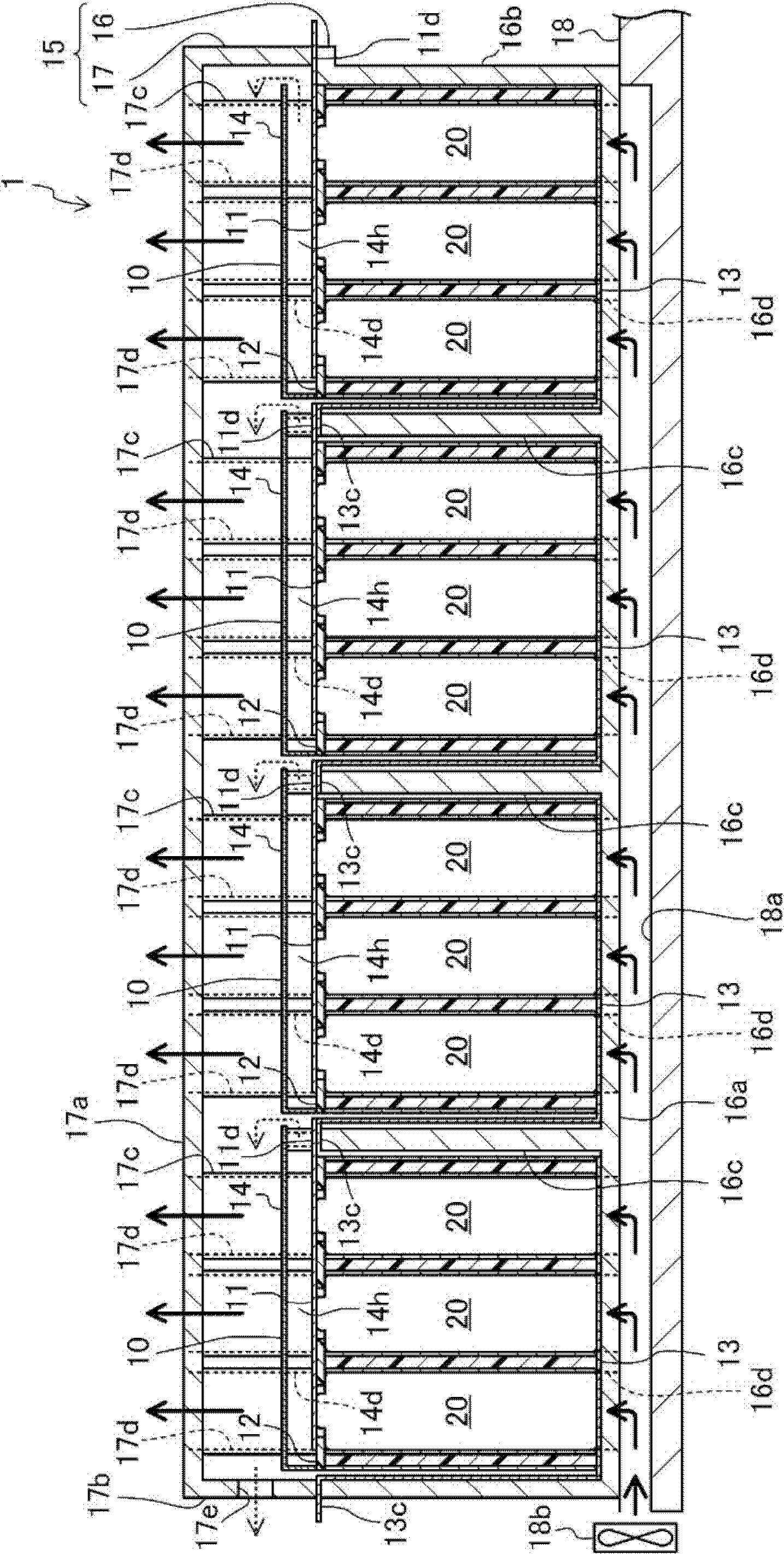
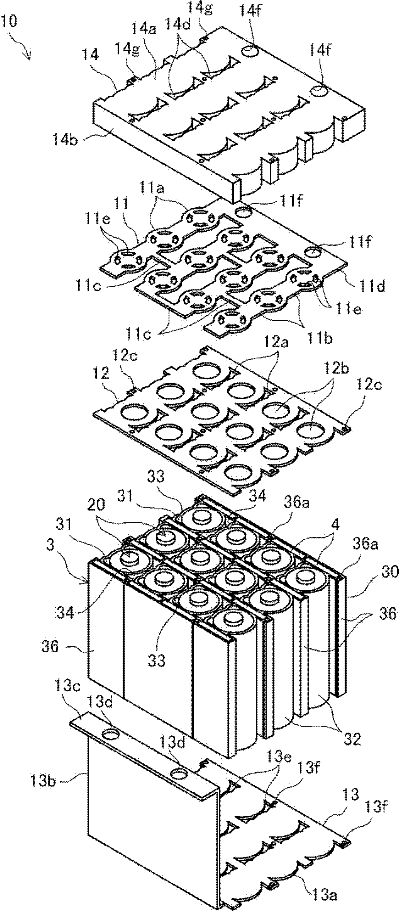
[0035] figure 1 A sectional view showing a battery module 1 according to an exemplary embodiment 1 of the present invention, figure 2 An exploded perspective view showing the battery unit. In addition, in figure 1 In , only the external shape of the unit cell 20 is shown.

[0036] The battery module 1 has: a plurality of single cells 20, 20...; supports 3, 3... for holding the single cells 20, 20...; positive connection plates 11, 11... connected to the positive poles of the single cells 20, 20...; Separators 12, 12... between the end faces of the positive side of the cells 20, 20... Cover members 14 , 14 . . . form a discharge space 14 h described later on the outside of the positive electrode side of the battery cells 20 , 20 . The battery module 1 is installed in, for example, a hybrid vehicle or an electric vehicle as a power source. exist figure 1 In the present invention, the battery module 1 is arranged on the floor 18 of the hybrid vehicle.

[0037] In the batt...

Embodiment approach 2

[0091] Hereinafter, an exemplary embodiment 2 of the present invention will be described. Figure 8 A partial enlarged plan view of the battery cell 210 showing a state in which the positive electrode connection plate 11 , the separator 12 , and the lid member 14 are omitted.

[0092] In the battery unit 210 of the second embodiment, the structure of the bracket 203 is different from that of the first embodiment. Therefore, the same reference numerals are assigned to the same configurations as those in Embodiment 1, and description thereof will be omitted, and the description will focus on different configurations.

[0093] The holder 203 has: a holder main body 230 provided with housing portions 231, 231, . Refrigerant channels 234, 234... on the holder main body 230; and phase change members 4, 4... provided on the holder main body 230 and changing from a solid phase to a liquid phase at a predetermined melting point. The pressing plate 233 constitutes a pressing portion, ...


PUM


Abstract

Disclosed is a battery module which holds unit cells while efficiently regulating the temperature thereof. A battery module (1) is equipped with a plurality of columnar unit cells (20, 20), and a holder (3) which holds the plurality of columnar unit cells (20, 20). The holder (3) has a plurality of cylindrical housings (31, 31) which house the unit cells (20,20 ), a plurality of coolant passages (34, 34) and phase-change members (4, 4) which regulate the temperature of the unit cells (20, 20), and a plurality of pressing walls (33, 33) which press the unit cells (20, 20) so that the outer peripheral surface of the unit cells (20, 20) comes into contact with the inner peripheral surface of the cylindrical housings (31, 31). The holder (3) is formed from an aluminium alloy.

Description

technical field [0001] The invention relates to a battery module with a plurality of individual cells. Background technique [0002] Conventionally, from the viewpoint of saving resources and energy, there has been an increasing demand for secondary batteries that can be used repeatedly. The secondary battery is used as a power source for driving various portable electronic devices such as mobile phones, digital cameras, video cameras, notebook computers, and mobile communication devices. Furthermore, in recent years, the demand for secondary batteries has increased due to the popularization of hybrid vehicles and electric vehicles. [0003] As such a secondary battery, a modular battery is known in which a plurality of general-purpose single cells are electrically connected. For example, in the battery module of Patent Document 1, a plurality of general-purpose single cells called "18650" are combined to form one battery module. Also, in the battery module, the plurality...

Claims


Application Information

Patent Timeline
Patent Type & Authority Applications(China)
IPC IPC(8): H01M10/50H01M2/10H01M10/60H01M10/613H01M10/623H01M10/625H01M10/643H01M10/647H01M10/653H01M10/6557H01M10/6561H01M10/6567H01M10/659H01M50/209H01M50/528
CPCH01M10/625H01M10/653H01M10/6563H01M10/647H01M10/6569H01M10/6557H01M10/6567H01M10/643H01M10/613H01M10/659Y02E60/10H01M50/213H01M50/209H01M10/6556F25D17/00H01M50/528
Inventor 高津克己
Owner PANASONIC CORP
Why Eureka
Try Eureka