Deep-sea non-contact electric power transmission packaging structure

A non-contact, power transmission technology, applied in circuit devices, circuits, inductors, etc., can solve the problems of short service life, high price, difficult implementation, etc., and achieve the effect of long service life, reliable connection and convenient operation.

Inactive Publication Date: 2012-02-29
ZHEJIANG UNIV
View PDF7 Cites 7 Cited by
  • Summary
  • Abstract
  • Description
  • Claims
  • Application Information

AI Technical Summary

Problems solved by technology

[0002] There are mainly two ways to connect power transmission cables in the deep sea: contact type and non-contact type. The contact type is the so-called wet plug connector, which still realizes the cable connection through the mutual contact between the conductors. This type of connector is expensive. The service life is short, and underwater robots are required to perform complex plug-in operations, which is difficult to realize; while using the principle of electromagnetic induction, the non-contact transmission of electric energy is realized. The Chinese patent underwater electric energy transmission non-contact connection device (public number CN 101667778A) and the non-contact connection device for underwater power and signal transmission (public number CN 101667777A) realize the non-contact transmission of power and electric signals. Because of the non-contact, this power transmission method has high reliability and long service life , but the above patents did not study in depth the reliable external packaging to deal with the harsh environment of the deep sea and how to facilitate the operation of underwater robots

Method used


Image

  • Deep-sea non-contact electric power transmission packaging structure
  • Deep-sea non-contact electric power transmission packaging structure

Examples


Embodiment Construction

[0017] Further illustrate the present invention below in conjunction with accompanying drawing:

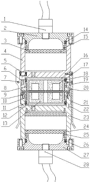
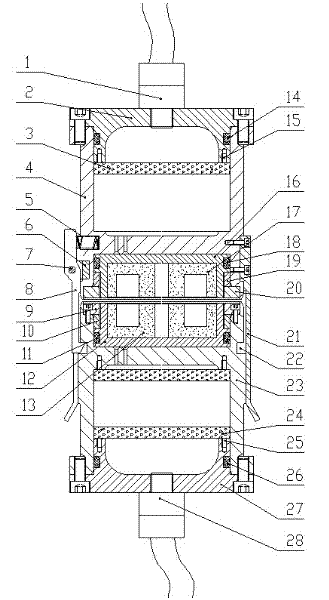
[0018] like figure 1 As shown, the packaging structure of the non-contact power transmission in the deep sea environment involved in the present invention includes a primary coupling joint and a secondary coupling joint;

[0019] The primary coupling joint includes a primary end face pressure ring 9, a primary sleeve 10, a primary magnetic core sealing ring 11, a primary magnetic core support frame 12, a primary magnetic core 13, a hook groove 22, a primary housing 23, a primary control circuit board 24, and a primary Circuit board installation hole 25, primary end cover sealing ring 26, primary end cover 27, primary watertight connector 28.

[0020] The primary watertight connector 28 is threadedly connected with the primary end cover 27, and the primary end cover 27 has a sealing groove, and the primary end cover sealing ring 26 is placed in the sealing groove, and the primary ...


PUM


Abstract

The invention discloses a deep-sea non-contact electric power transmission packaging structure. By using the prior art, a deep-sea severe environment can not be coped with and robot operation can not be performed conveniently under the sea. The packaging structure of the invention comprises: a primary coupling joint and a secondary coupling joint. The primary coupling joint is designed with a magnetic core cavity, a control cavity and a card hook groove. The secondary coupling joint is designed with the magnetic core cavity, the control cavity, a guide plate and a card hook mechanism. Primary and secondary docking mechanisms are arranged out of the two joints. After the primary coupling joint and the secondary coupling joint form a coaxial docking, magnetic cores in the two left and right magnetic core cavities of contact surfaces are correctly coupled with each other and electric power is transmitted. After the transmission ends, the docking mechanisms break. In the invention, a reasonable sealing structure is designed. A waterproof connector is connected with an underwater cable. The deep-sea extreme environment, such as a high pressure and strong corrosion can be coped with. The structure is stable and reliable. The internal system is not easy to be influenced by seawater disturbance. A plugging form is simple. The underwater robot is very suitable for the docking operation. A service life is long.

Description

technical field [0001] The invention belongs to the technical field of deep-sea electromechanical packaging, and relates to a packaging structure that satisfies non-contact power transmission in deep-sea environments and is suitable for underwater robot operations. Background technique [0002] There are mainly two ways to connect power transmission cables in the deep sea: contact type and non-contact type. The contact type is the so-called wet plug connector, which still realizes the cable connection through the mutual contact between the conductors. This type of connector is expensive. The service life is short, and underwater robots are required to perform complex plug-in operations, which is difficult to realize; while using the principle of electromagnetic induction, the non-contact transmission of electric energy is realized. The Chinese patent underwater electric energy transmission non-contact connection device (public number CN 101667778A) and the non-contact co...

Claims


Application Information

Patent Timeline
Patent Type & Authority Applications(China)
IPC IPC(8): H02J17/00H01F38/14H02J50/00
Inventor 李德骏陆晴云陈鹰
Owner ZHEJIANG UNIV
Why Eureka
Try Eureka