Turbine wheel with untuned blades comprising a damping device

A technology for turbine impellers and blades, which is applied in the directions of blade support elements, safety devices, mechanical equipment, etc., can solve problems such as expensive dampers

Inactive Publication Date: 2012-02-29
TURBOMECA SA
View PDF6 Cites 7 Cited by
  • Summary
  • Abstract
  • Description
  • Claims
  • Application Information

AI Technical Summary

Problems solved by technology

However, the use of dampers can be very expensive as their effect can only be verified late in the design process by testing the engine

Method used


Image

  • Turbine wheel with untuned blades comprising a damping device
  • Turbine wheel with untuned blades comprising a damping device
  • Turbine wheel with untuned blades comprising a damping device

Examples


Embodiment Construction

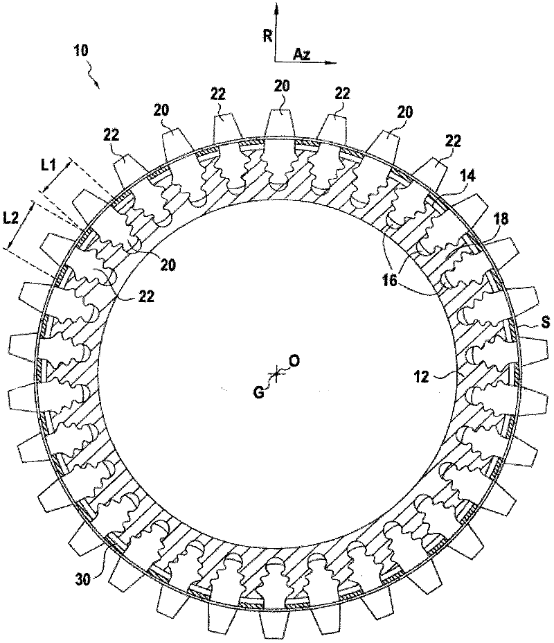
[0050] The embodiment of FIG. 1 represents a turbine wheel 10 as typically found in a turbomachine, such as a helicopter gas turbine 100 . Generally, a gas turbine, such as the gas turbine shown in FIG. 4 , includes a high pressure turbine 102 rotationally driven by a hot gas flow exiting a combustor 104 . High pressure turbine 102 drives rotation of compressor 106 to compress fresh air into gas turbine 100 and bring the fresh air into combustor 104 where it is mixed with fuel for combustion purposes.

[0051] The excess hot gas flow exiting the high pressure turbine 102 is used to drive the free turbine 108 in rotation. This turbine is specifically connected to the main rotor of the helicopter to drive it in rotation.

[0052] The inventive turbine wheel 10 can advantageously be applied in a high-pressure turbine 102 or indeed in a free turbine 108 .

[0053] Referring again to FIG. 1 , it can be seen that the turbine wheel 10 is comprised of a disk 12 having a center O and...


PUM


Abstract

The present invention relates to a turbine wheel (10) comprising: - a plurality of first blades (20) and a plurality of second blades (22), at least one of the first blades being adjacent to at least one of the second blades; a disc (12) having an axis of rotation, at a periphery of which the blades are mounted, each of the blades having a tip secured to a root engaged in a housing (16) opening at the periphery of the disc, each of the blades comprising a polarizing means consisting of a ledge positioned between the tip and the root of the said blade, the ledges of the first blades (20) having an azimuthal length (L1) different from the azimuthal length (L2) of the ledges of the second blades (22); a damping device (30) positioned at least between the said two adjacent blades, the said damping device being positioned between the ledges of the blades (20, 22) and the periphery of the disc (12); the mass of the roots (22b) of the second blades (22) is less than the mass of the roots (20b) of the first blades (20) while the profiles of the tips (20a, 22a) of the first and second blades are identical, the result of this being that the resonant frequency of the first blades is different from the resonant frequency of the second blades, and the second blades (22) are engineered to break before the first blades (20) if the turbine wheel begins to overspeed.

Description

technical field [0001] The present invention relates to the field of turbine wheels, such as will be found particularly, but not exclusively, in turbomachines, such as gas turbines. Such impellers may be found, for example, in high pressure turbines or freewheeling turbines. [0002] The invention relates more particularly to turbine wheels comprising: [0003] · multiple blades; and [0004] • A disc having a rotating shaft with blades mounted on its periphery, each blade having a solid head with a root which itself engages in a recess opening towards the periphery of the disc. Background technique [0005] It is known that turbine wheels, especially when operating in turbine engines, are subject to large vibrations from vibratory exciting forces. [0006] In some cases, these vibration excitations can generate high levels of vibration that are detrimental and can lead to fracture of the turbine wheel. If the vibration excitation causes the turbine wheel to go into reso...

Claims


Application Information

Patent Timeline
Patent Type & Authority Applications(China)
IPC IPC(8): F01D5/16F01D5/14F01D5/22
CPCF01D5/141F01D5/16F01D5/22F01D21/045F05D2220/40Y10S416/50
Inventor 马克·迪裘德吉恩-飞利浦·奥斯蒂
Owner TURBOMECA SA
Why Eureka
Try Eureka