U-shaped concrete beam bridge girder erection machine

A technology of girder erecting machine and concrete girder, which is applied in the direction of bridges, bridge construction, erection/assembly of bridges, etc. It can solve problems such as inaccurate control of the center of gravity, inability to withstand concentrated forces, and excessive moment of bridge pier capping girders, etc., to improve construction quality, reduce construction cost and difficulty, and facilitate bridge construction

Inactive Publication Date: 2012-03-07
TENGDA CONSTR GROUP CORP +1
View PDF6 Cites 25 Cited by
  • Summary
  • Abstract
  • Description
  • Claims
  • Application Information

AI Technical Summary

Problems solved by technology

Since the U-shaped concrete beam is an open cross-section, and has the shape characteristics of large top and small bottom, left and right asymmetry, and a relatively thin bottom plate, the U-shaped concrete beam itself cannot withstand large concentrated forces and has weak torsion resistance.
If the traditional bridge erecting machine is directly used to erect the girder, the force of the outriggers configured on the girder is too concentrated to easily damage the girder bottom plate and the moment to the pier cover girder is too large, and the center of gravity cannot be accurately grasped when lifting the U-shaped concrete girder , it is ...

Method used


Image

  • U-shaped concrete beam bridge girder erection machine
  • U-shaped concrete beam bridge girder erection machine
  • U-shaped concrete beam bridge girder erection machine

Examples


Embodiment Construction

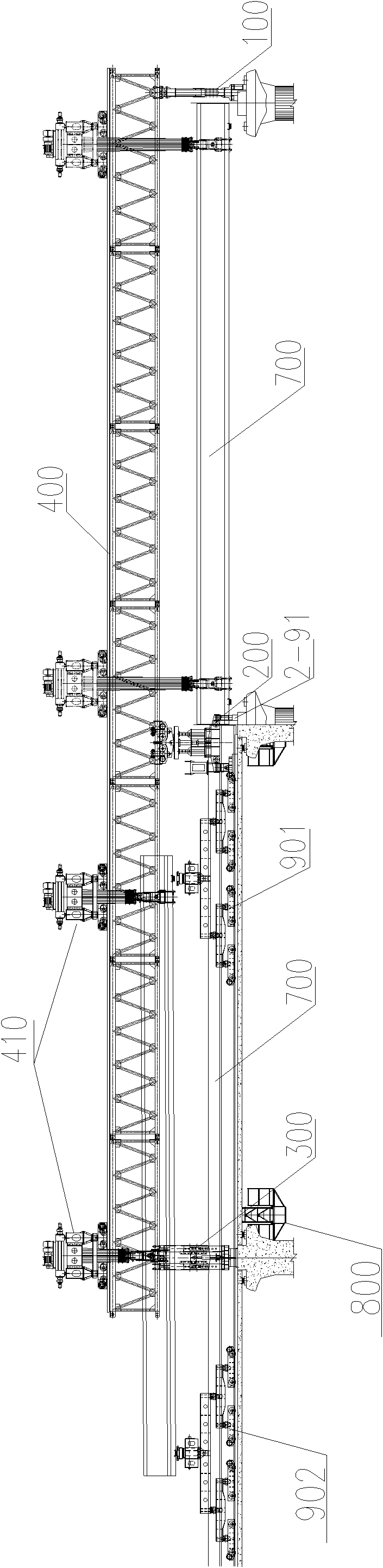
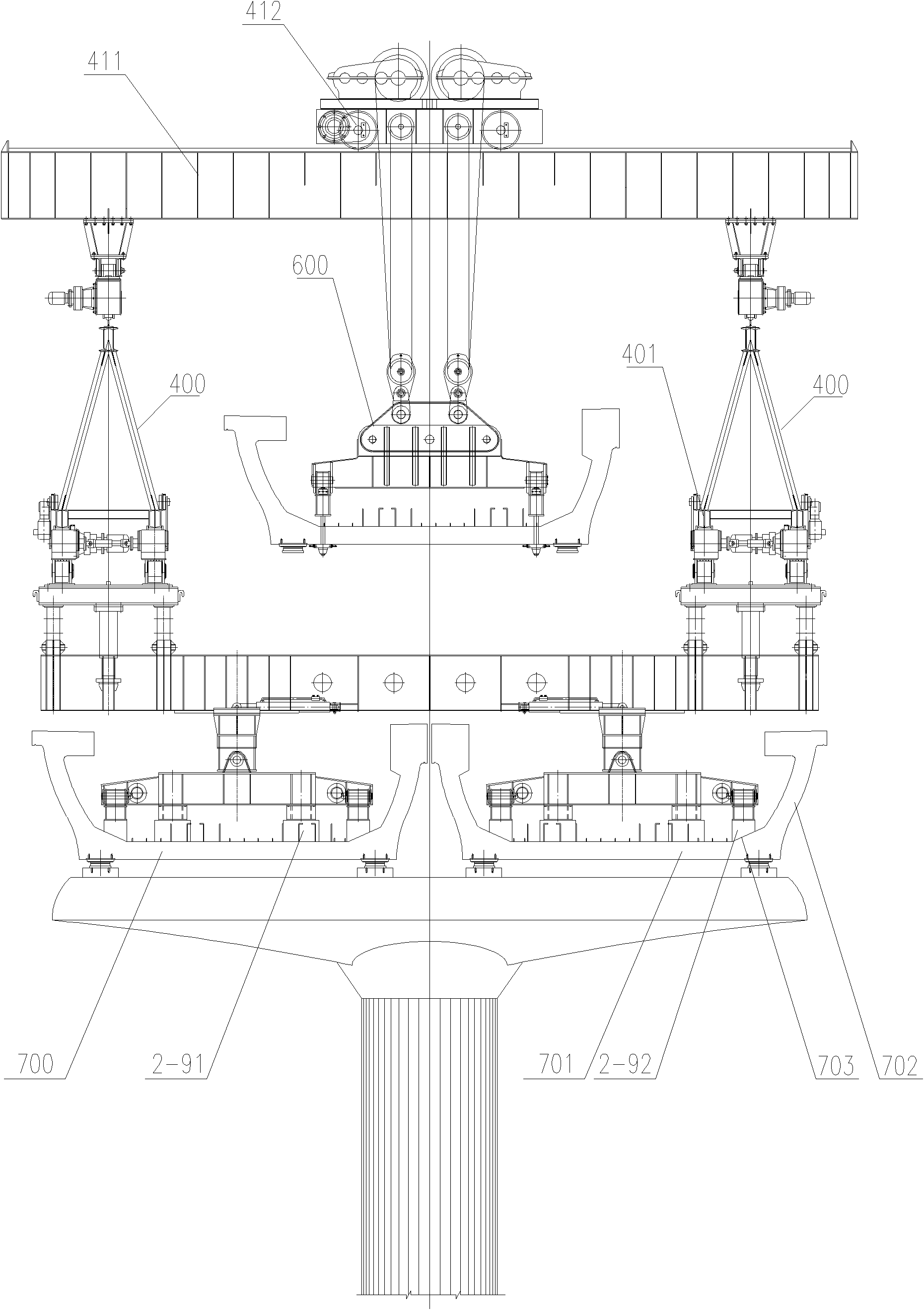
[0043] The present invention includes the main girder 400 of the bridge erecting machine, two cranes 410 traveling on the front and rear of the main girder of the bridge erecting machine, the retractable No. 1 outrigger 100, the No. 2 outrigger 200, the No. 3 outrigger 300, and the U-shaped concrete beam Spreader 600, the crane is provided with a crane beam 411 and a crane lateral motion mechanism 412 walking on the beam, the U-shaped concrete beam spreader is connected with the crane lateral motion mechanism, and the bridge erecting machine is also equipped with Front and rear beam transport trolleys 901, 902 and temporary track 500 thereof.

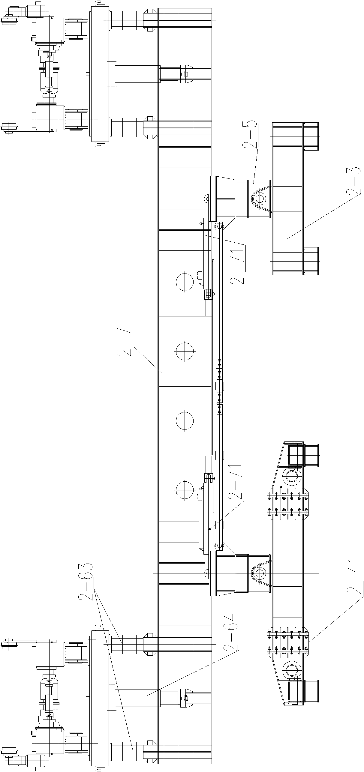
[0044] Refer to attached Figure 1-6 . The second outrigger 200 is the middle outrigger of the bridge erecting machine, which includes two sets of left and right outrigger mechanisms. The outrigger mechanism is provided with a multi-level "distribution beam-pad pier" structure. Including a front pier 2-1 and a rear pier 2-2; the front...


PUM


Abstract

The invention provides a U-shaped concrete beam bridge girder erection machine, which comprises a bridge girder erection machine main beam, a front crown block, a back crown block, a telescopic No. 1 landing leg, a telescopic No. 2 landing leg, a telescopic No. 3 landing leg and a U-shaped concrete beam hanger, wherein the front crown block and the back crown block walk on the bridge girder erection machine main beam, and are provided with crown block transverse beams and crown block transverse moving mechanisms walking on the transverse beams; the U-shaped concrete beam hanger is connected with the crown block transverse moving mechanisms; and the bridge girder erection machine is further provided with a hanging construction platform, a front beam conveying trolley, a back beam conveyingtrolley and a temporary rail. In the invention, an original bridge girder erection machine can be improved specific to the characteristics of a U-shaped concrete beam, so that the problem of bridge girder erection caused by a U-shaped beam structure can be solved; convenience is brought to bridge girder erection construction according to the characteristics of the U-shaped beam structure, so thatthe bridge girder erection machine provided by the invention is suitable for U-shaped concrete beams; and crane hoisting or gantry crane installation is not required in U-shaped concrete bridge girder erection, so that the construction cost and difficulty can be greatly lowered, and the construction quality can be improved.

Description

technical field [0001] The invention relates to the field of bridging machinery. Background technique [0002] U-shaped concrete beam, as a kind of down-loaded structural section, has the advantages of good noise reduction effect, low building height, and high utilization rate of section space. Generally, it is constructed by factory prefabrication and transported to the site for installation, and has been applied in many rail transits at home and abroad. Since the U-shaped concrete beam is an open section, and has the shape characteristics of large top and small bottom, left and right asymmetry, and a relatively thin bottom plate, the U-shaped concrete beam itself cannot bear large concentrated forces and has weak torsion resistance. If the traditional bridge erecting machine is directly used to erect the girder, the force of the outriggers configured on the girder is too concentrated to easily damage the girder bottom plate and the moment to the pier cover girder is too l...

Claims


Application Information

Patent Timeline
IPC IPC(8): E01D21/00
Inventor 孙九春巩立辉邵长春潘春风薛武强李海洋蔡冰冰张璐宗祥杨九如
Owner TENGDA CONSTR GROUP CORP
Why Eureka
Try Eureka