
Line head wiping method

An inkjet head and line type technology, applied in printing and other directions, can solve the problems of not being able to wipe the line type inkjet head cleanly and ink residue, etc., and achieve the effects of prolonging life, preventing premature wear, and preventing the surrounding area from being stained

Inactive Publication Date: 2012-03-14
MIYAKOSHI PRINTING MACHINERY
View PDF10 Cites 7 Cited by
  • Summary
  • Abstract
  • Description
  • Claims
  • Application Information

AI Technical Summary

Problems solved by technology

[0008] Therefore, when wiping the entire lower surface of the carriage as described above, as the wiping of the head bottom surface progresses, the ink adhering to the front end of the wiper enters the above-mentioned groove, and the lower surface of the line type inkjet head cannot be wiped cleanly.
[0009] In addition, even when the nozzle head of the line type inkjet head is mounted on the carriage so that the head bottom surface of the nozzle head of the line type inkjet head is on the same plane as the lower surface of the carriage, the nozzle head of the line type inkjet head may sometimes be damaged due to dimensional errors. In this case, even if the front end of the squeegee is bent and comes into contact with the lower surface of the carriage, ink will remain around the bottom of the head, as described above. Cannot cleanly wipe the lower surface of the line inkjet head

Method used


Image

  • Line head wiping method
  • Line head wiping method
  • Line head wiping method

Examples


Embodiment Construction

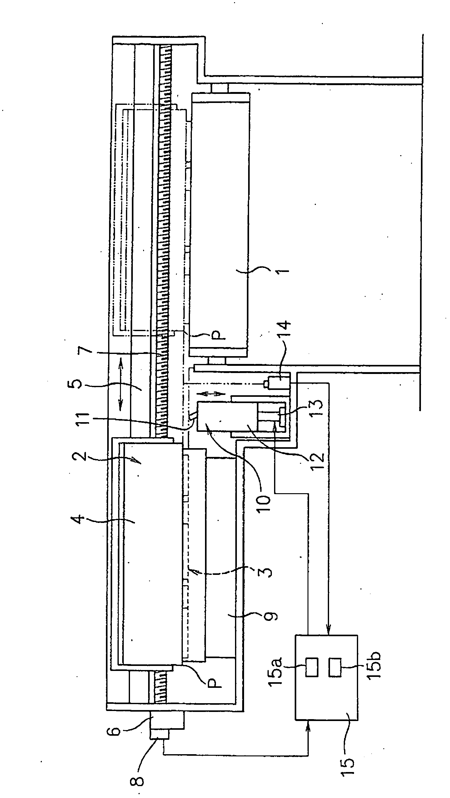
[0024] figure 2 It is an explanatory diagram schematically showing an inkjet recording apparatus for carrying out the method of the present invention. Reference numeral 1 in the figure is a conveying device (platen) for conveying a recording medium (recording paper) in a direction at right angles to the figure, and reference numeral 2 is located on the upper side of the conveying device 1 and spreads over the conveying device. 1 print head that prints across the entire width of the conveyed recording medium. A line inkjet head 3 facing across the entire width of the continuous paper is provided on the lower surface of the print head 2 via a carriage 4 supported by the print head 2 .

[0025] The print head 2 is guided by the guide rail 5 between the printing area and the maintenance area, and moves under the action of the feed screw 7 driven and rotated by the motor 6. An area where the head 3 prints with a predetermined printing width on the recording medium, and the above...


PUM


Abstract

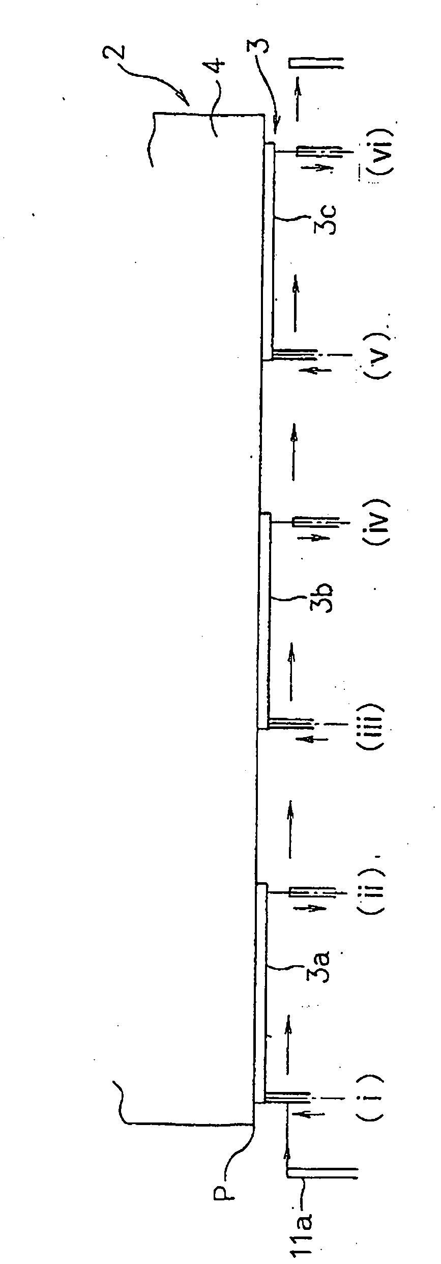
A method of wiping a line blade with a blade is disclosed that prevents premature wear and break of the blade and preserving its elastic deformation from soiling the environment. Accordingly, a plurality of nozzle heads (3a, 3b, 3c, 3d, 3e) are arranged in a direction of printing width and supported by a carriage (4) to form the line head (3), wherein the head bottom face of each of the nozzle heads of the line head is wiped with a blade moved relative thereto in a direction of printing width, the plurality of nozzle heads is a nozzle face in which a number of open ink nozzles are formed, the nozzle face is lied centrally of the head bottom face in a direction of printing width and is flush with the head bottom face, and the wiping is effected with an end of the blade brought into contact with the head bottom face from a position between one end of the head bottom face in the direction of printing width and the corresponding one end of the nozzle face to a position between the other end of said head bottom face in the direction of printing width and the corresponding other end of the nozzle face.

Description

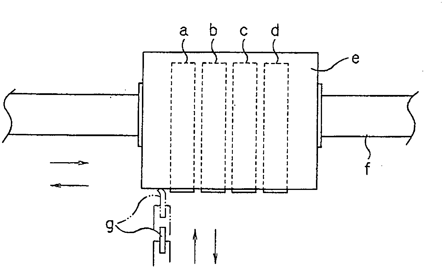
technical field [0001] The present invention relates to a wiping method of a line head for wiping (wiping) a nozzle surface of a print head constituting an inkjet recording device. Background technique [0002] As this wiping method, the following techniques are known: figure 1 As shown, when the carriage e is moved from the printing area to the wiping area along the guide rail f, the scraper (blade) g is raised from the lower side of the carriage e to the front end where the front end interferes with the protrusions of the nozzle heads a to d. As the above-mentioned carriage e moves, use the front end of the scraper g to wipe the nozzle surface as the end surface of the protruding front end of each nozzle head a to d along the lower surface of the carriage e. For wiping, the above-mentioned carriage e is formed by protruding from the lower surface of the carriage with the front ends having the nozzle faces of the plurality of nozzle heads a, b, c, d (refer to Japanese Pate...

Claims


Application Information

Patent Timeline
Patent Type & Authority Applications(China)
IPC IPC(8): B41J2/165
CPCB41J2/16538B41J2/16544B41J2/16588B41J2/16541
Inventor 井泽秀男石川晃板桥渡
Owner MIYAKOSHI PRINTING MACHINERY
Learn More