Pressing assembly of embossed stamp machine

A technology of stamping machines and components, applied in printing, stamping, etc., which can solve the problems of large rebound force and unsmooth operation and use, and achieve the effects of reduced reaction force, smooth use, and reduced downforce

Active Publication Date: 2012-03-14
SUN SAME ENTERPRISES
View PDF6 Cites 2 Cited by
  • Summary
  • Abstract
  • Description
  • Claims
  • Application Information

AI Technical Summary

Problems solved by technology

[0004] In the above structure, the user can push the upper mold 81 to move towards the lower mold 82 by using the pressing handle 92, and then clamp the object to be imprinted. At the same time, the upper mold 81 of the embossing unit 80 will exert a reaction force on the pressing member 94, thereby pushing the pressing member 94 and the co-moving pressing handle 92, causing the user to hold the pressing handle 92 relatively. The hand of the stencil printing machine will receive a lot of rebound force
Therefore, in the design of the pressing components of the existing stamping machine, it is necessary to apply a huge amount of downward pressure to make the embossing marks obvious, and the greater the downward pressure, the greater the reaction force of the pressing components for the user, resulting in operational problems. Not going well

Method used


Image

  • Pressing assembly of embossed stamp machine
  • Pressing assembly of embossed stamp machine
  • Pressing assembly of embossed stamp machine

Examples


Embodiment Construction

[0052] The technical means adopted by the present invention to achieve the intended purpose of the invention will be further described below in conjunction with the accompanying drawings and preferred embodiments of the present invention.

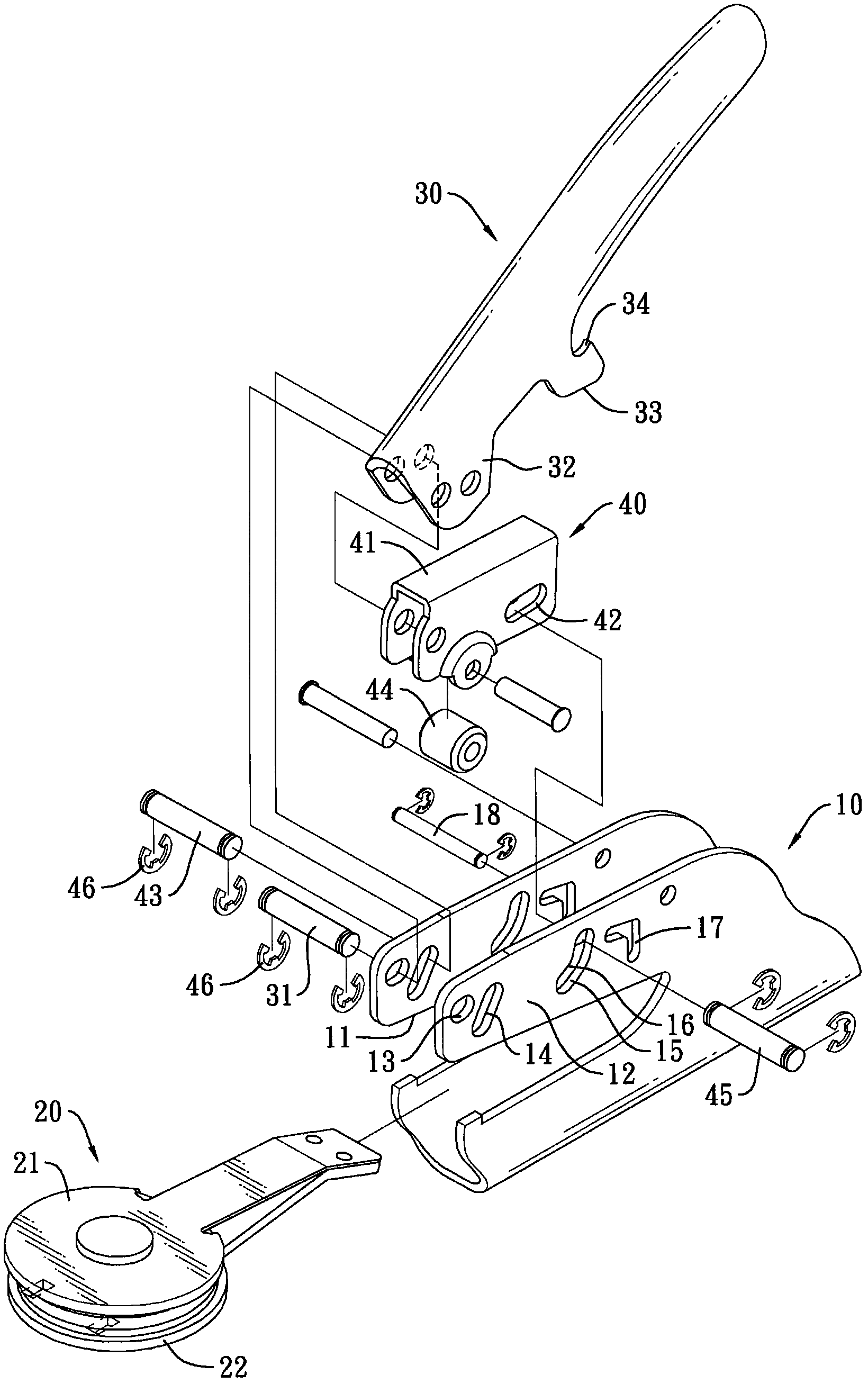
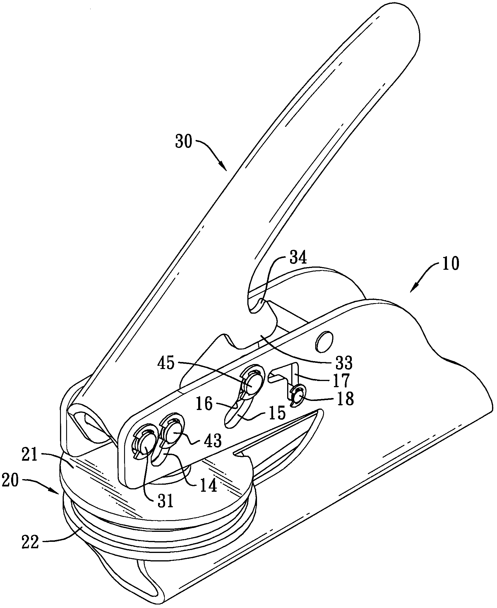
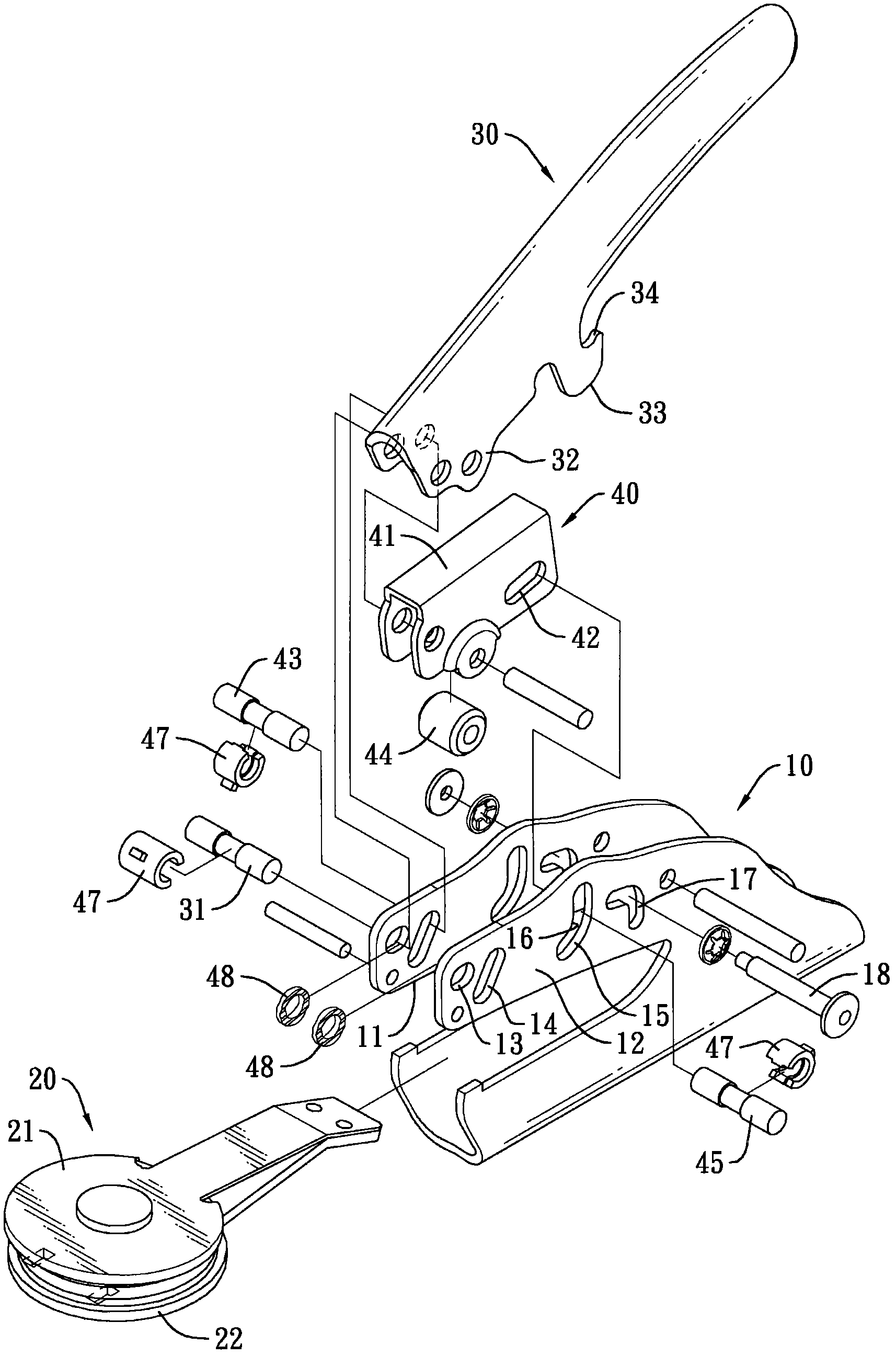
[0053] see Figure 1 to Figure 5, which are several specific embodiments of the pressing components of the stencil stamping machine of the present invention, which include a base 10, a pressing handle 30 and a pressing member 40, and can further provide an embossing unit 20 assembled to form a stencil stamping machine , wherein the embossing unit 20 includes an upper mold 21 and a lower mold 22 .

[0054] The front end of the base 10 is provided with a clamping groove 11, the clamping groove 11 can be assembled by the embossing unit 20, and the upper part of the clamping groove 11 is provided with two plate parts 12 at intervals, and the second plate part 12 is provided with The pivot hole 13 , the slide slot 14 and the buffer slot 15 are ...


PUM


Abstract

The invention relates to a pressing assembly of an embossed stamp machine. The pressing assembly comprises a base which is used for arranging an embossing unit, a pressing handle which is pivoted on the base, and a pressing member which is pivoted on the base and positioned below the pressing handle and adjacently kept close to the embossing unit, wherein the pressing handle is stressed by a downforce, and through a force moment, the pressing handle drives the pressing member through a first pushing part and a second pushing part of the pressing handle to increase the force for pressing downthe pressing member so that the pressing member presses against the embossing unit; besides, when the down force is reduced, the pressing member moves upwards under a reaction force of the embossing unit, is stopped by a convex part in a buffer slot of the base in the process, consumes the reaction force acting on the pressing member, and lightens the upwards-moving power of a pressure rod at thesame time, so that the embossed stamp machine is more labor-saving and handy in use.

Description

technical field [0001] The invention relates to a pressing assembly of a stamping machine, in particular to a pressing assembly for a user to hold and apply force to make the stamping unit of the stamping machine carry out stamping. Background technique [0002] see Figure 8 As shown, the existing stamping machine includes a pressing assembly and an embossing unit 80, the pressing assembly includes a base 90, the front end of the base 90 is provided with a locking groove 91, and the embossing unit 80 can be assembled In the clamping groove 91, the embossing unit 80 includes an upper mold 81 and a lower mold 82. The base 90 is pivotally connected to a pressure handle 92 by a pivot 93 above the clamping groove 91. The pressure handle 92 has a first end and a second end, the first end is away from the pivot joint between the pressure handle 92 and the base 90, and the second end is adjacent to the pivot joint between the pressure handle 92 and the base 90 and the second end i...

Claims


Application Information

Patent Timeline
IPC IPC(8): B41K3/62
Inventor 施旭昇
Owner SUN SAME ENTERPRISES
Why Eureka
Try Eureka