Cutting tool and cutting insert therefor

一种切削刀片、切削工具的技术,应用在切削刀片、工具夹、制造工具等方向,能够解决限制切削刀片最小尺寸、限制等问题

Active Publication Date: 2012-03-14
ISCAR LTD
View PDF6 Cites 4 Cited by
  • Summary
  • Abstract
  • Description
  • Claims
  • Application Information

AI Technical Summary

Problems solved by technology

[0003] However, a concave-convex mating surface in the clamping area, when applied to both the upper and lower surfaces of the insert clamping portion, has the disadvantage that it limits the minimum size of the cutting insert and thus the smallest concave surface that can be achieved. Groove diameter size

Method used


Image

  • Cutting tool and cutting insert therefor
  • Cutting tool and cutting insert therefor
  • Cutting tool and cutting insert therefor

Examples


Embodiment Construction

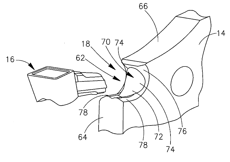
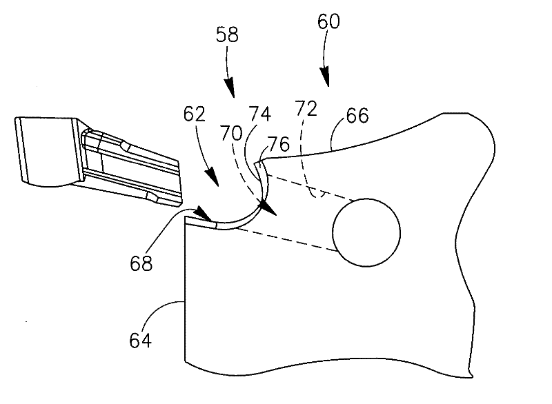
[0031] First, a description of the cutting portion 10 of the cutting tool 12 according to the embodiment of the present invention is shown. figure 1 with figure 2 Pay attention. The cutting tool 12 includes an insert seat 14 and a cutting insert 16, wherein the cutting insert 16 is figure 1 is fixed in the insert groove 18 of the insert seat 14, and in figure 2 The middle cutting insert 16 has been removed from the insert pocket 18 .

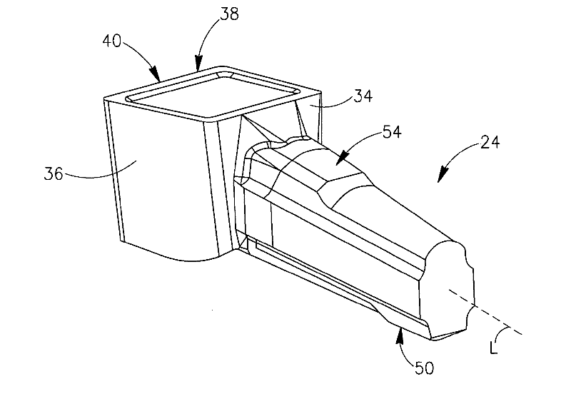
[0032] Figures 3 to 8 The cutting insert 16 is shown in detail. The cutting insert 16 has a cutting portion 20 at a forward end 22 of the cutting insert 16 and an elongated positioning portion 24 extending rearwardly from the cutting portion 20 . The cutting insert 16 is preferably, but not necessarily, made of cemented carbide, such as tungsten carbide. The cutting insert 16 can be made by pressing or injection molding as well as sintering processes. The cutting insert 16 may also be ground. The elongated positioning portion 24 has a...


PUM


Abstract

A cutting tool has a cutting insert releasably retained in an insert pocket. The insert pocket includes a supporting portion having support surfaces and a clamping portion including a socket having a socket wall, the socket extending rearwardly from the supporting portion. The cutting insert has a cutting portion with front abutment surfaces and an elongated locating portion extending rearwardly from the cutting portion. The cutting insert is retained in the insert pocket with the front abutment surfaces abutting the support surfaces and with the locating portion located in the socket with abutment surfaces of the locating portion in abutment with the socket wall.

Description

technical field [0001] The present invention relates to a cutting insert and a cutting tool, not exclusively, for grooving, turning, parting and facing grooving. Background technique [0002] For example in U.S. Patent No. 5,709,508 figure 2 A typical prior art face grooving tool is shown in , in which the cutting insert is held in a groove formed between an upper jaw and a curved lower jaw. The grooves are open on each side of the cutting insert, which not only weakens the structure of the cutting tool in the groove area, but also means that the cutting insert has no inherent retention in the lateral direction and thus in metal cutting operations This period leads to lateral instability of the cutting insert. Obviously, this is a problem not only for facing grooving tools, but also for non-face grooving tools. In order to keep the cutting insert stable against lateral forces, the jaws of the tool and the upper and lower surfaces of the cutting insert can be as described ...

Claims


Application Information

Patent Timeline
Patent Type & Authority Applications(China)
IPC IPC(8): B23B27/04B23B29/04
CPCB23B27/045B23B29/043B23B2240/32Y10T407/2268Y10T407/2288Y10T407/2272Y10T407/2282Y10T407/24B23B27/04B23B27/16B23B29/04B23B2200/08
Inventor G.赫克特
Owner ISCAR LTD
Why Eureka
Try Eureka