

DC voltage compensation in a multi-terminal hvdc power transmission network
A power transmission and network technology, applied in the field of active voltage source devices, can solve problems such as high cost
- Summary
- Abstract
- Description
- Claims
- Application Information
AI Technical Summary
Problems solved by technology
Method used
Image

Examples
Embodiment Construction
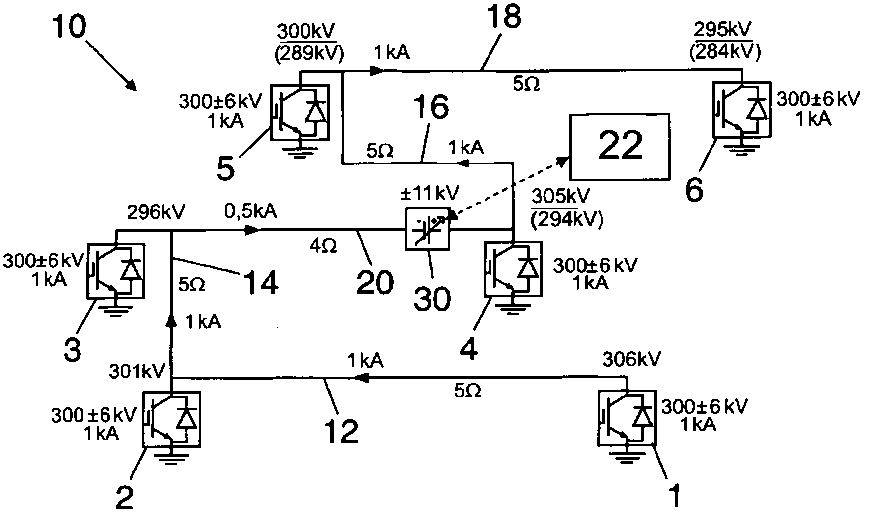
[0031] figure 1 A multi-terminal HVDC power transmission network 10 is shown in the form of a non-mesh network and in particular in the form of linear interconnections. Assume that initially there are three double-ended HVDC links and these three double-ended HVDC links are operated independently of each other, wherein the first HVDC link comprises a converter station 1 and a converter station 2. The second HVDC link includes converter station 3 and inverter station 4 interconnected by transmission line 20 , while the third HVDC link includes inverter station 5 and inverter station 5 interconnected by transmission line 18 Station 6. Afterwards, the first HVDC link and the second HVDC link are connected by introducing a transmission line 14 between the converter station 2 and the converter station 3, while between the converter station 4 and the converter station 5 A transmission line 16 is introduced between the second HVDC link and the third HVDC link. The result obtained ...
PUM
 Abstract
Description
Claims
Application Information