High-rigidity redundantly-actuated three-degree-of-freedom parallel mechanism

A technology with a degree of freedom and high rigidity, which is applied in the direction of metal processing machinery parts, large fixed members, metal processing equipment, etc., can solve problems such as unrealizable, high rigidity, and poor bearing capacity of the mechanism, and achieve easy control, high rigidity, and manufacturing The effect of cost reduction

Active Publication Date: 2012-03-21
ZHEJIANG SCI-TECH UNIV
View PDF16 Cites 26 Cited by
  • Summary
  • Abstract
  • Description
  • Claims
  • Application Information

AI Technical Summary

Problems solved by technology

[0005] The two-transfer-one-transfer three-degree-of-freedom parallel mechanism disclosed in several patent applications submitted by the applicant (CN102126216A, CN102126217A) and the approved patent (CN101518898A) does not have accompanying motion, and has the characteristics of simple structure and low manufac...

Method used


Image

  • High-rigidity redundantly-actuated three-degree-of-freedom parallel mechanism
  • High-rigidity redundantly-actuated three-degree-of-freedom parallel mechanism
  • High-rigidity redundantly-actuated three-degree-of-freedom parallel mechanism

Examples


Embodiment 1

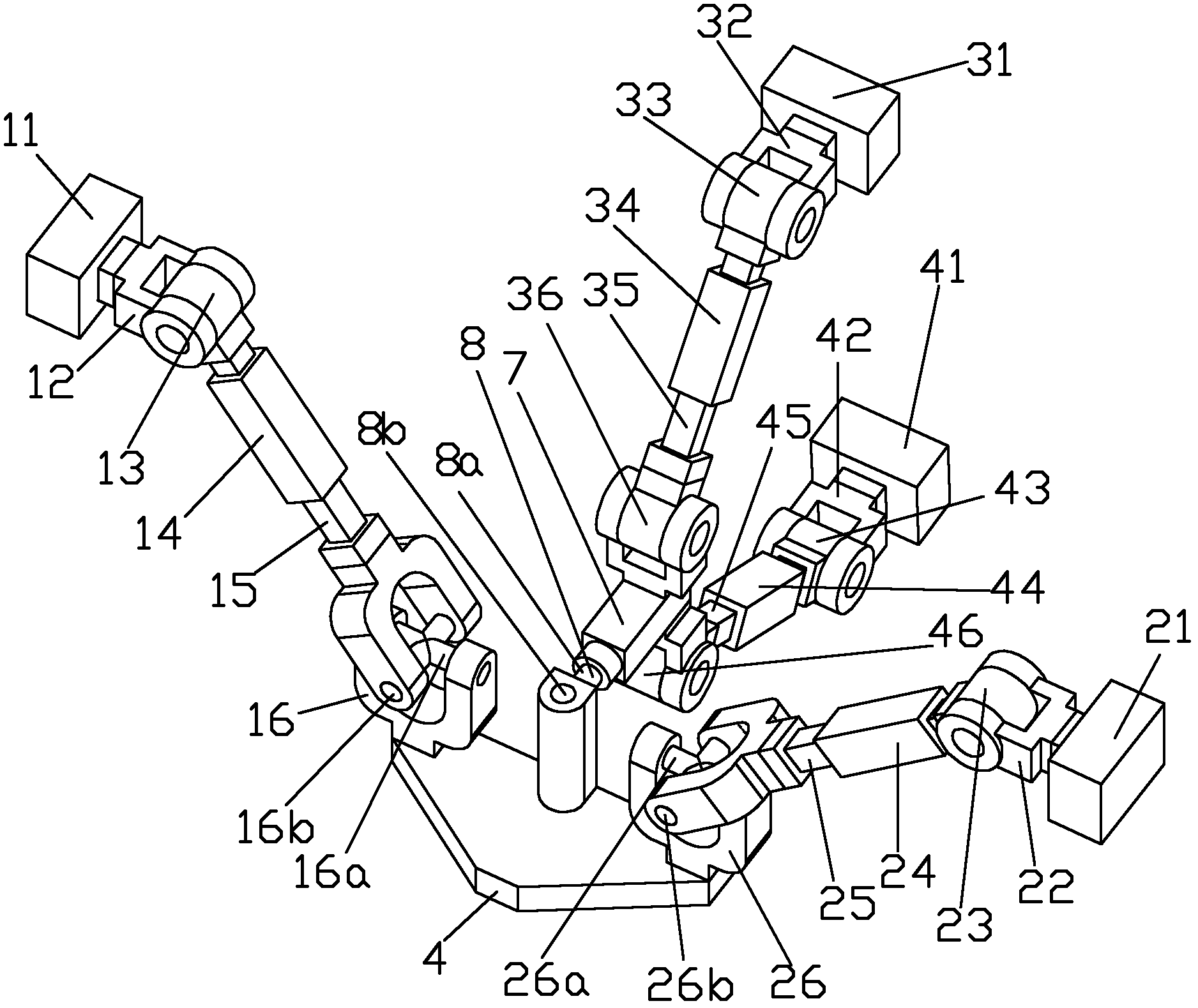
[0025] like figure 1 As shown, the moving platform 4 is connected with the frame 11, the frame 21, the frame 31 and the frame 41 through three branches; the first single-degree-of-freedom kinematic pair and the second single-degree-of-freedom kinematic pair in the first branch are respectively The rotating pair 13 and the moving pair 14, the frame 11 are connected with the moving platform 4 through the first connecting rod 12, the rotating pair 13, the moving pair 14, the second connecting rod 15 and the universal hinge 16 in turn; the first in the second branch The single-degree-of-freedom kinematic pair and the second single-degree-of-freedom kinematic pair are the rotating pair 23 and the moving pair 24 respectively, and the frame 21 passes through the first connecting rod 22, the rotating pair 23, the moving pair 24, the second connecting rod 25 and the universal The hinge 26 is connected with the moving platform 4; the first single-degree-of-freedom kinematic pair and the...

Embodiment 2

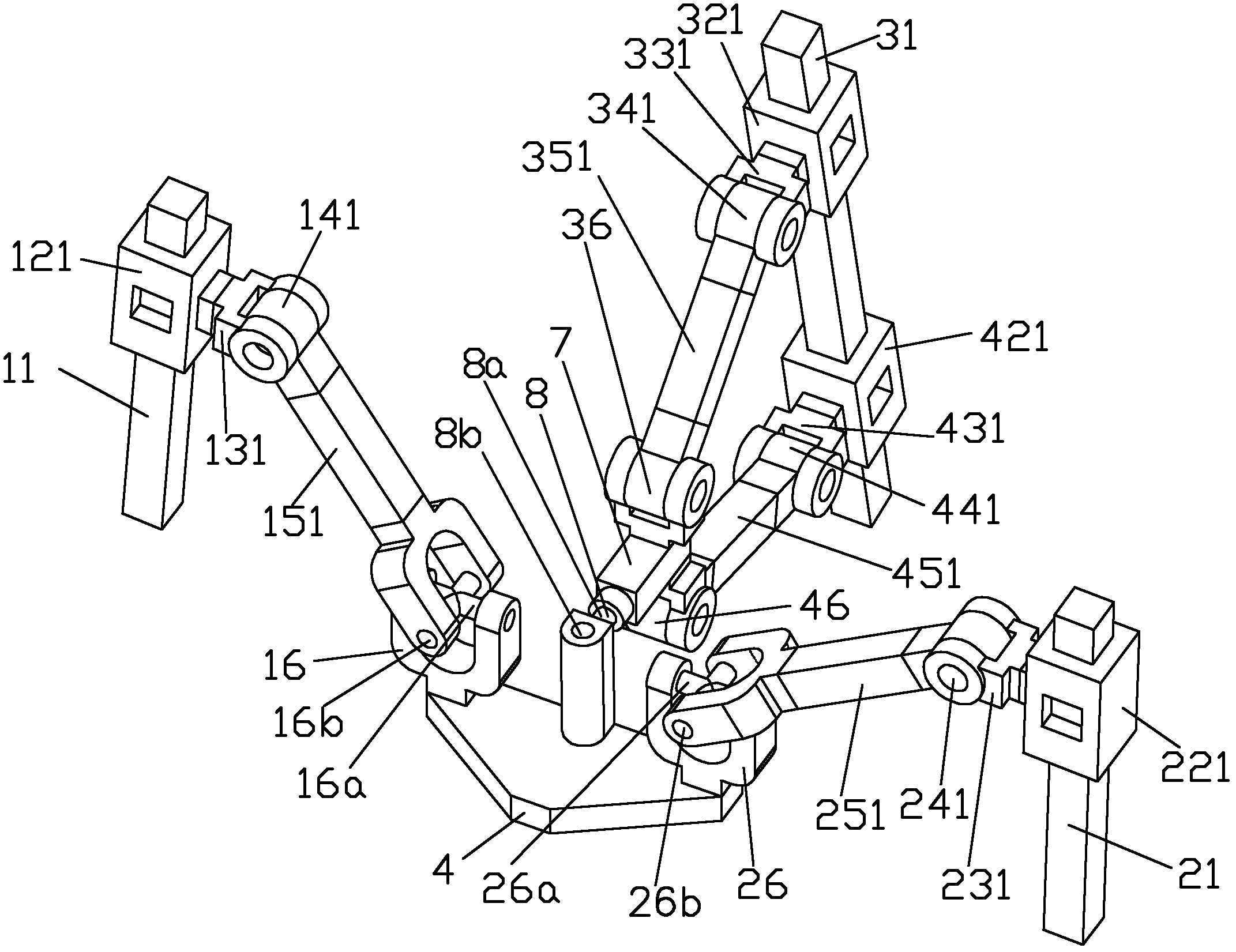
[0028] like figure 2As shown, the moving platform 4 is connected with the frame 11, the frame 21, and the frame 31 through three branches; the first single-degree-of-freedom kinematic pair and the second single-degree-of-freedom kinematic pair in the first branch are respectively the mobile pair 121 and the second single-degree-of-freedom kinematic pair. The rotating pair 141, the frame 11 is connected with the moving platform 4 through the moving pair 121, the first connecting rod 131, the rotating pair 141, the second connecting rod 151 and the universal hinge 16 in turn; the first single degree of freedom movement in the second branch pair and the second single-degree-of-freedom kinematic pair are respectively a moving pair 221 and a rotating pair 241. The platform 4 is connected; the first single-degree-of-freedom kinematic pair and the second single-degree-of-freedom kinematic pair of the first branch chain in the third branch are respectively the moving pair 321 and the...

Embodiment 3

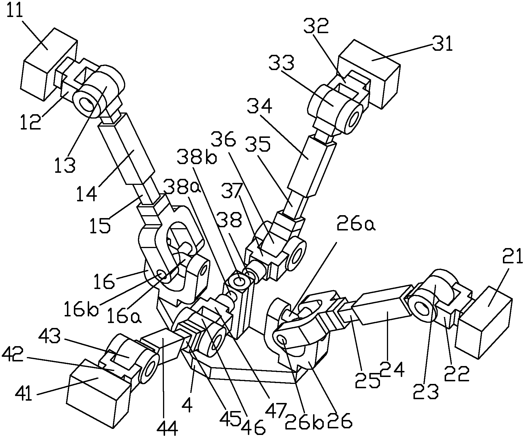
[0034] like image 3 As shown, the moving platform 4 is connected with the frame 11, the frame 21, the frame 31 and the frame 41 through three branches; the first single-degree-of-freedom kinematic pair and the second single-degree-of-freedom kinematic pair in the first branch are respectively The rotating pair 13 and the moving pair 14, the frame 11 are connected with the moving platform 4 through the first connecting rod 12, the rotating pair 13, the moving pair 14, the second connecting rod 15 and the universal hinge 16 in turn; the first in the second branch The single-degree-of-freedom kinematic pair and the second single-degree-of-freedom kinematic pair are the rotating pair 23 and the moving pair 24 respectively, and the frame 21 passes through the first connecting rod 22, the rotating pair 23, the moving pair 24, the second connecting rod 25 and the universal The hinge 26 is connected with the moving platform 4 . The two branches in the third branch are distributed sy...


PUM


Abstract

The invention relates to a fewer-degree-of-freedom robot mechanism. The aim of the invention is to provide a mechanism which has the characteristic of improved rigidity and bearing capacity. The invention adopts a technical scheme that the high-rigidity redundantly-actuated three-degree-of-freedom parallel mechanism comprises a dynamic platform, a machine frame, a first branch, a second branch and a third branch, wherein each of the first branch and the second branch is connected with a first single-degree-of-freedom kinematic pair, a second single-degree-of-freedom kinematic pair and a universal hinge in turn. The fewer-degree-of-freedom robot mechanism is characterized in that: the third branch is divided into two parallel branch chains; each branch chain is connected with the first single-degree-of-freedom kinematic pair, the second single-degree-of-freedom kinematic pair and a rotation pair in turn; the first rotation axis line of the universal hinge of the first branch and the first rotation axis line of the universal hinge of the second branch are in the same line and pass through the central point of the T-shaped hinge of the third branch; and the first rotation axis line of the T-shaped hinge of the third branch is vertical or parallel to the rotation axis line of the universal hinge of the first branch and the rotation axial line of the universal hinge of the second branch.

Description

technical field [0001] The invention relates to a robot mechanism with few degrees of freedom, in particular to a three-degree-of-freedom parallel mechanism with high rigidity redundant drive. Background technique [0002] Parallel robots with few degrees of freedom and less than 6 degrees of freedom are currently the focus of international parallel robotics academia and industry. In practical applications, there are a considerable number of operating tasks that require less than 6 degrees of freedom. At this time, the application of a suitable parallel robot with fewer degrees of freedom can effectively save the cost of system design, manufacturing, control and maintenance. [0003] The 3-DOF parallel mechanism with two rotation degrees of freedom and one movement degree of freedom (referred to as 2 rotations and 1 movement) is a very important class of parallel robots with few degrees of freedom. The 3-PRS / RPS type parallel mechanism is a typical representative of the two...

Claims


Application Information

Patent Timeline
IPC IPC(8): B23Q1/54
Inventor 陈巧红李秦川余旭锋武传宇
Owner ZHEJIANG SCI-TECH UNIV
Why Eureka
Try Eureka