Sliding positioning mechanism

一种定位机构、滑动件的技术,应用在支承机器、机械设备、机台/支架等方向,能够解决系统构造复杂、成本高等问题

Inactive Publication Date: 2012-03-21
HONG FU JIN PRECISION IND (SHENZHEN) CO LTD +1
View PDF11 Cites 12 Cited by
  • Summary
  • Abstract
  • Description
  • Claims
  • Application Information

AI Technical Summary

Problems solved by technology

However, the above-mentioned mechanism that can realize multi-position positioning has a relatively complicated system structure and high cost

Method used


Image

  • Sliding positioning mechanism
  • Sliding positioning mechanism
  • Sliding positioning mechanism

Examples


Embodiment Construction

[0011] The sliding positioning mechanism of the present invention will be further described in detail in conjunction with the accompanying drawings and specific embodiments.

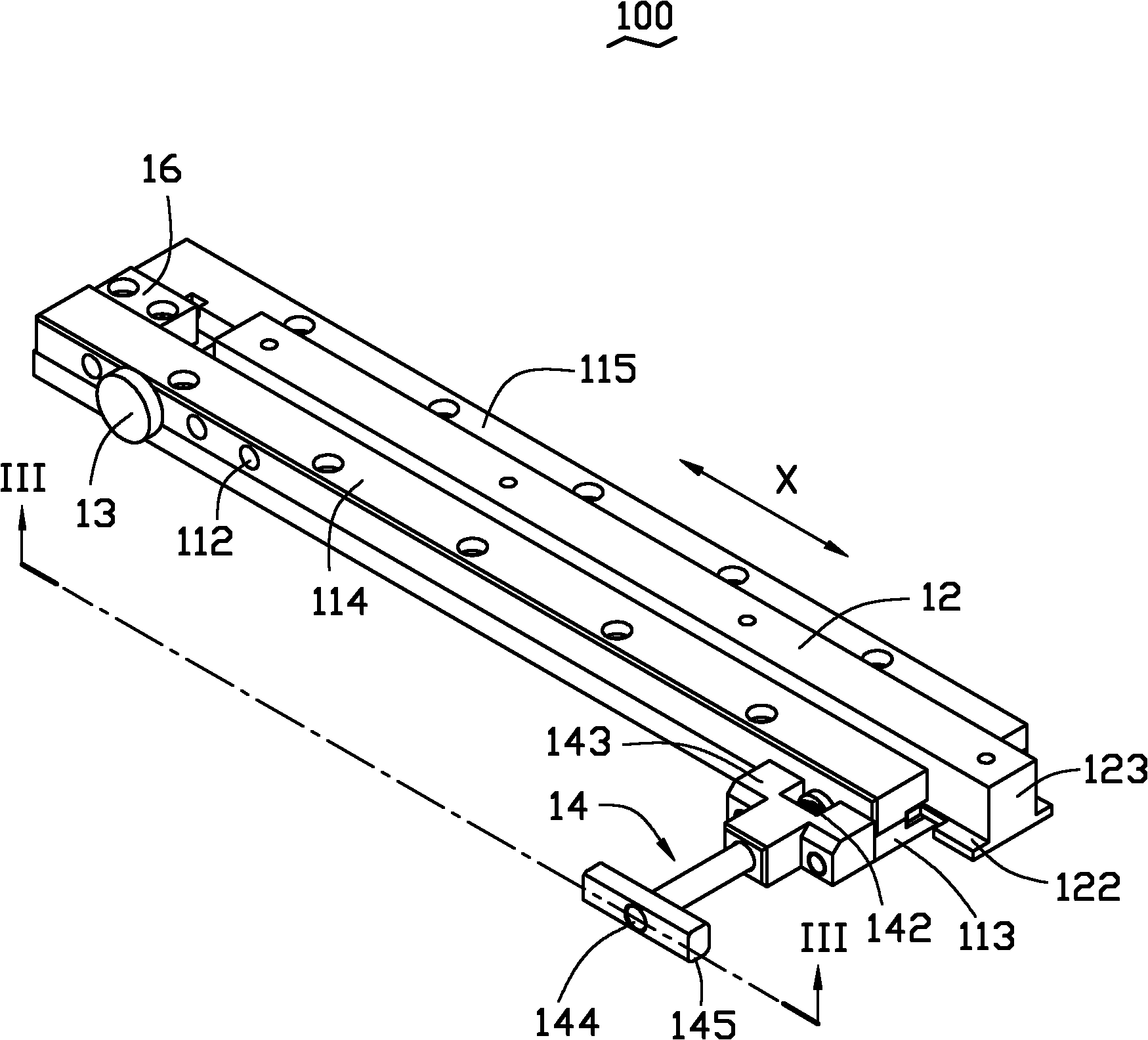
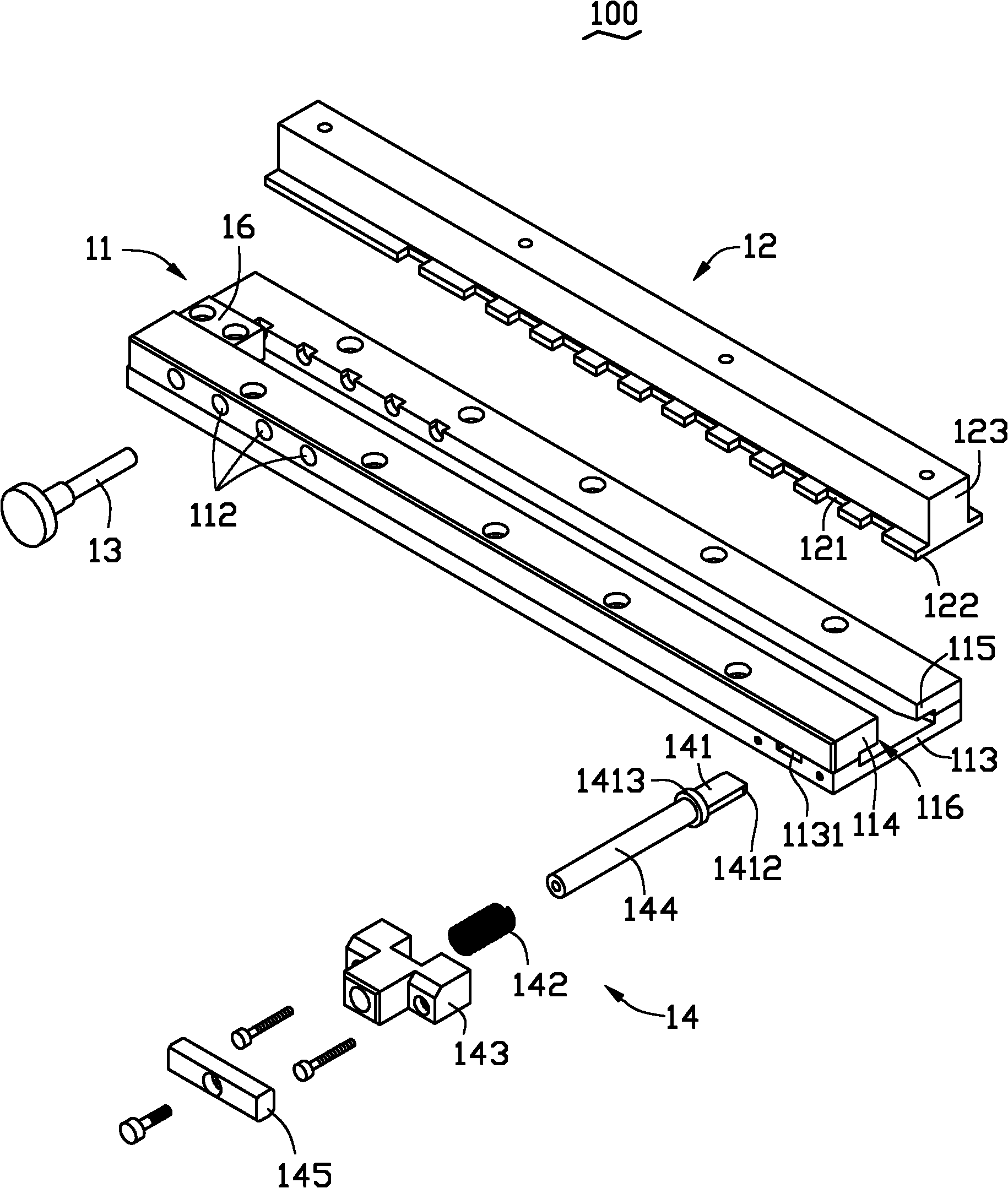
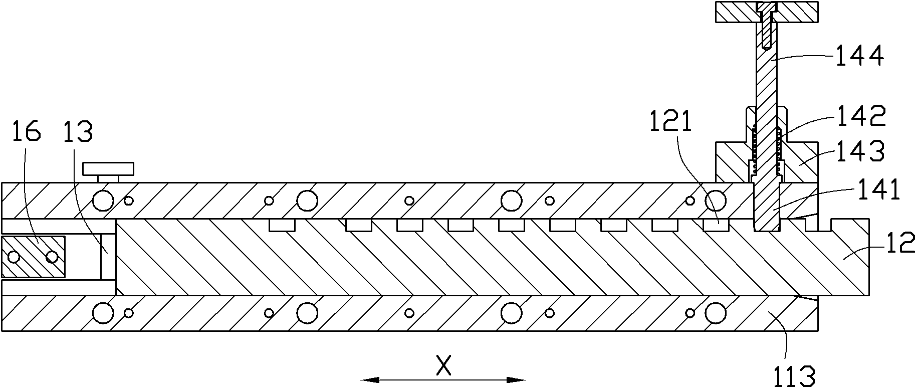
[0012] See Figure 1 to Figure 3 , the sliding positioning mechanism 100 according to the embodiment of the present invention includes a main body 11 , a sliding part 12 slidably fitted with the main body, a coarse positioning part 13 and a precise positioning component 14 . The sliding member 12 can slide along the sliding direction X relative to the body 11 . The coarse positioning member 13 and the precise positioning component 14 respectively roughly and precisely position the sliding member 12 relative to the main body 11 , so as to jointly position the sliding member 12 .

[0013] The main body 11 defines a plurality of positioning holes 112 arranged along the sliding direction X. As shown in FIG. The coarse positioning member 13 passes through one of the positioning holes 112 and cooperates with ...


PUM


Abstract

The invention provides a sliding positioning mechanism which comprises a main body, a sliding piece which is in sliding fit with the main body and can slide along with a sliding direction, a crude positioning component and an accurate positioning component. The main body is provided with a plurality of positioning holes which are arranged along the sliding direction, the crude positioning component penetrates through one positioning hole and is matched with the sliding piece so as to crudely position the sliding piece, the sliding piece is provided with a plurality of positioning grooves which are arranged along the sliding direction, the accurate positioning component comprises a clamping piece which is matched with one positioning groove so as to accurately position the sliding piece and an elastic piece which elastically and bias presses the clamping piece along the direction which is adjacent to the sliding piece. The sliding positioning mechanism has the advantages of simple structure, convenient operation and multi-position positioning.

Description

technical field [0001] The invention relates to a sliding positioning mechanism, in particular to a sliding positioning mechanism capable of realizing multi-position positioning. Background technique [0002] In the process of automatic film application or automatic marking, it is necessary to accurately position the workpiece on the machine table. The usual practice is to fix a special fixture on the machine table, and then clamp the workpiece to the fixture, because the position of the fixture relative to the machine table is determined, so that the workpiece can be positioned. However, in this way, the position of the workpiece is relatively fixed and cannot be adjusted, and it is difficult to realize the positioning of multiple positions. Generally, a driving mechanism connected to the special fixture can be set, such as a screw-nut mechanism, or a gear-rack mechanism, etc. to drive the fixture, and the fixture can be positioned in multiple positions through the control...

Claims


Application Information

Patent Timeline
Patent Type & Authority Applications(China)
IPC IPC(8): B25B11/00
CPCF16M11/043F16M2200/028
Inventor 陈文生赵智明
Owner HONG FU JIN PRECISION IND (SHENZHEN) CO LTD
Why Eureka
Try Eureka