
Blow mold

A technology of blow mold and bottom mold, which is applied in the field of blow mold, which can solve the problems of large installation space and achieve the effect of shortening the cycle time, saving the time of locking the bottom mold, and spending less time

Inactive Publication Date: 2012-03-21
KRONES AG
View PDF5 Cites 10 Cited by
  • Summary
  • Abstract
  • Description
  • Claims
  • Application Information

AI Technical Summary

Problems solved by technology

Performs very fast and complex movements which, due to their superposition, must be controlled very precisely and require complex motion drives requiring large installation spaces

Method used


Image

  • Blow mold
  • Blow mold
  • Blow mold

Examples


Embodiment Construction

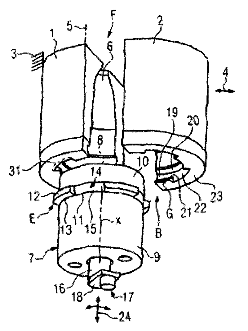
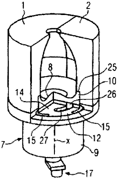
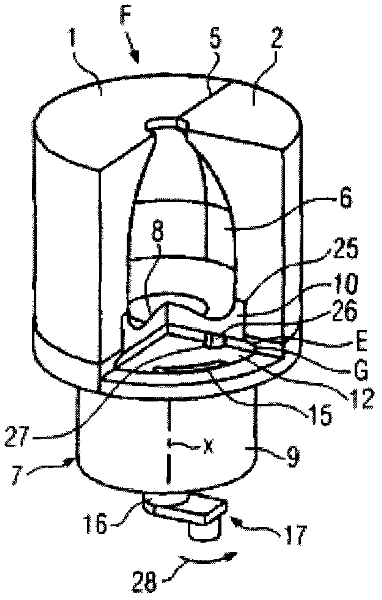
[0023] figure 1 The blow mold F in is used, for example in a blow molding operation or a stretch blow molding operation, to manufacture containers from preforms, which blow mold F is mounted in a blow molding station not shown of the blow molding machine. Here, the blow mold F is shown in the state without the normally provided mold support device and includes a fixed mold half 1 (also called a shell mold) as a main part and can be positioned relative to the fixed Mold half 1 moves the other mold half 2. The movable mold half 2 can be folded open about a not shown axis or moved linearly (as shown) by means of a kinematic drive 4 not shown in more detail. The mold halves 1 , 2 can be closed in a closed position with the other mold half 2 in the mold parting plane 5 and can be locked to each other under the action of locking pressure, for example by means of not shown mold support means. The stent half 1 is fixed to a support 3, for example.

[0024] The bottom mold 7 is anot...


PUM


Abstract

A blow mold (F) with a stationary mold half (1) and another mold half (2) movable relative to the stationary mold half between closed and open positions, and having a bottom mold (7) comprising a bottom mold axis (X) essentially perpendicular to the moving direction of the other mold half which can be moved relative to the mold halves (1, 2) between an engaged position and a removal position, and which can be at least positively locked with the mold halves in the engaged position and the closed position of the other mold half by at least one collar-like engaging element (E) at the bottom mold, and a ring groove-like counterengagement structure (G) in the mold halves, the engaging element (E) and at least the counterengagement structure form a bayonet catch (B) in the stationary mold half which can be actuated by relative rotary motions of the engaging element about the bottom mold axis and only linear relative movements in the direction of the bottom mold axis.

Description

technical field [0001] The invention relates to a blow mold comprising a fixed mold half, at least one further mold half movable relative to the fixed mold half between a closed position and an open position, a bottom mold and optionally Drives for synchronous motion of the other mold half and the bottom mold, the bottom mold comprising a bottom mold axis substantially perpendicular to the direction of movement of the other mold half, the bottom mold being able to be in an engaged position and a removed position relative to the mold half and the bottom mold can be at least positively locked with the mold half in the engaged position and the closed position of the other mold half by at least one engaging element and a corresponding engagement structure in the form of an annular groove in the mold half so that the bottom mold cannot Moving in the direction of movement of the bottom mold, the engagement element protrudes outward in the form of a flange and is at least approximate...

Claims


Application Information

Patent Timeline
Patent Type & Authority Applications(China)
IPC IPC(8): B29C49/56B29C49/48
CPCB29C49/48B29C49/56B29C2049/4892B29C2049/566B29C49/5608B29C49/5612B29C2049/5661
Inventor 克里斯汀·斯多波
Owner KRONES AG
Learn More