Electric vehicle pantograph

A technology for electric vehicles and pantographs, applied to electric vehicles, vehicle parts, collectors, etc., can solve the problems of unbalanced load, no protection, normal lifting and other problems, and achieve the effect of prolonging the service life and simple structure

Inactive Publication Date: 2012-03-21
SHANGHAI AOWEI TECH DEV
View PDF5 Cites 5 Cited by
  • Summary
  • Abstract
  • Description
  • Claims
  • Application Information

AI Technical Summary

Problems solved by technology

When the pantograph starts charging, the multi-stage air (or hydraulic) cylinder 2 drives the multi-stage guide column 3 to rise together. Since the multi-stage air (or hydraulic) cylinder 2 and the multi-stage guide column 3 are linked, it strengthens the The rigidity of the pantograph after it is raised, but this linkage structure is prone to unbalanced loads during the travel process, resulting in problems of uneven stress between the multi-level guide column connections and failure to lift normally, resulting in failures
In addition, the wires connected to the power receiving board 4 are exposed and unprotected, which poses a certain potential safety hazard

Method used


Image

  • Electric vehicle pantograph
  • Electric vehicle pantograph
  • Electric vehicle pantograph

Examples


Embodiment Construction

[0016] Specific embodiments of the present invention will be described in detail below in conjunction with the accompanying drawings.

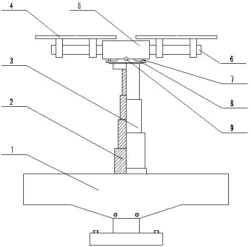
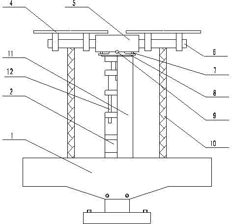
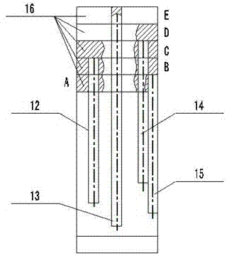
[0017] Such as figure 2 As shown, an electric vehicle pantograph of the present invention includes a shield 1 , a transmission device fixed on a base, a receiving plate 4 , and a beam frame composed of a beam 5 , a pin shaft 9 , and a support seat 8 . The transmission device is a multi-stage air (or hydraulic) cylinder 2, and there are multiple guide rods 12 on the multi-stage air (or hydraulic) cylinder 2. Such as image 3 Shown, off-center guide rod 12,13,14,15 is fixed on the flange 16 (comprising A, B, C, D, E five stages) of multistage gas (or hydraulic pressure) cylinder, and multistage gas ( (or hydraulic) cylinder structure integration, instead of the original multi-stage gas (or hydraulic) cylinder of the original pantograph linkage multi-stage telescopic guide column. The multi-stage air (or hydraulic) cylinder is not easy to rot...


PUM


Abstract

The invention provides an electric vehicle pantograph, which comprises the following components: a transmission device fixed on a base, a powered panel, and a beam frame consisting of a beam, a pin shaft and a support seat, wherein the transmission device is a multistage cylinder, and multiple guide rods are on the multistage cylinder. Because multiple guide rods are on the multistage cylinder, the electric vehicle pantograph in the invention makes the multistage cylinder be safer and reliable in elevating process, and simple in structure. Meanwhile, because a drag chain and a protective cover are added, the pantograph is more beautiful and safe, and the service life of the pantograph is prolonged.

Description

technical field [0001] The invention relates to an electric vehicle pantograph. Background technique [0002] Chinese patent ZL200710094281.1 discloses an electric vehicle pantograph, such as figure 1 As shown, it includes a power transmission device fixed on the base, a power receiving plate 4 and a beam frame composed of a beam 5 , a pin shaft 9 and a support base 8 . The interior of the power transmission device is a multi-stage telescopic transmission mechanism, and the exterior is a multi-stage telescopic guide column 3 . When the pantograph starts charging, the multi-stage air (or hydraulic) cylinder 2 drives the multi-stage guide column 3 to rise together. Since the multi-stage air (or hydraulic) cylinder 2 and the multi-stage guide column 3 are linked, it strengthens the The rigidity of the pantograph after it is raised, but this linkage structure is prone to unbalanced loads during the travel process, resulting in problems of uneven stress between the multi-level ...

Claims


Application Information

Patent Timeline
Patent Type & Authority Applications(China)
IPC IPC(8): B60L5/32
Inventor 梁全顺姜琦钱辉农谷珍
Owner SHANGHAI AOWEI TECH DEV
Why Eureka
Try Eureka