Supercharge Your Innovation With Domain-Expert AI Agents!

Cooling tank stirring device with diversion cover

A stirring device and shroud technology, applied in quenching devices, heat treatment equipment, manufacturing tools, etc., can solve the problems of low quenching oil temperature, long quenching time, high quenching oil temperature, etc., achieve uniform temperature, simple structure, and quenching uniform performance

Inactive Publication Date: 2012-03-21
苏州新凌电炉有限公司
View PDF0 Cites 2 Cited by
  • Summary
  • Abstract
  • Description
  • Claims
  • Application Information

AI Technical Summary

Problems solved by technology

In the existing quenching process, the metal parts to be processed should be quenched with quenching oil in the cooling tank. Generally, the quenching time is relatively long. Over time, the specific components in the quenching oil will sink. In this way, the bottom of the cooling tank The quenching hardness of the processed metal parts may be much higher than the quenching hardness of the processed parts in the upper part of the cooling tank, resulting in uneven quenching performance of the same batch of processed metal parts
At the same time, during the quenching process, the temperature of the cooling tank will also be uneven, the temperature of the quenching oil on the surface of the cooling tank is low, and the temperature of the quenching oil at the bottom of the cooling tank is high, resulting in uneven quenching performance of the processed metal parts

Method used


Image

  • Cooling tank stirring device with diversion cover
  • Cooling tank stirring device with diversion cover
  • Cooling tank stirring device with diversion cover

Examples


Embodiment Construction

[0014] The present invention will be further described below in conjunction with the accompanying drawings and embodiments.

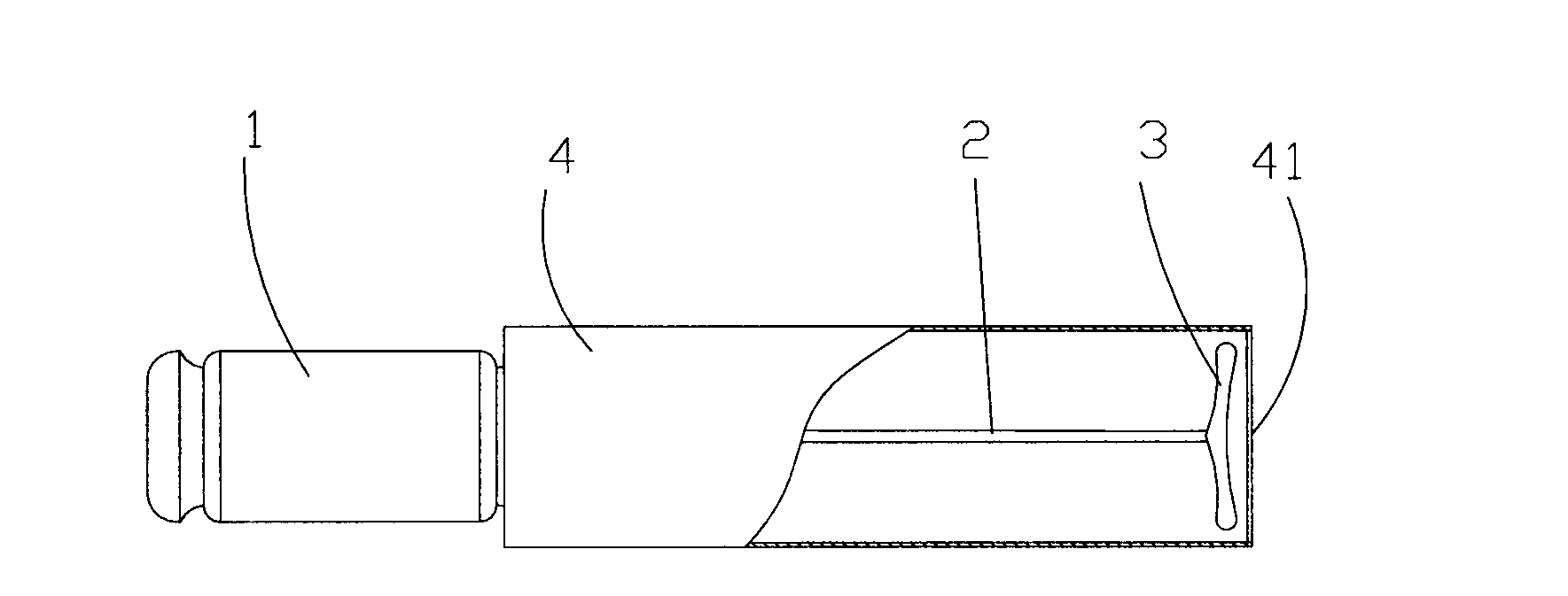
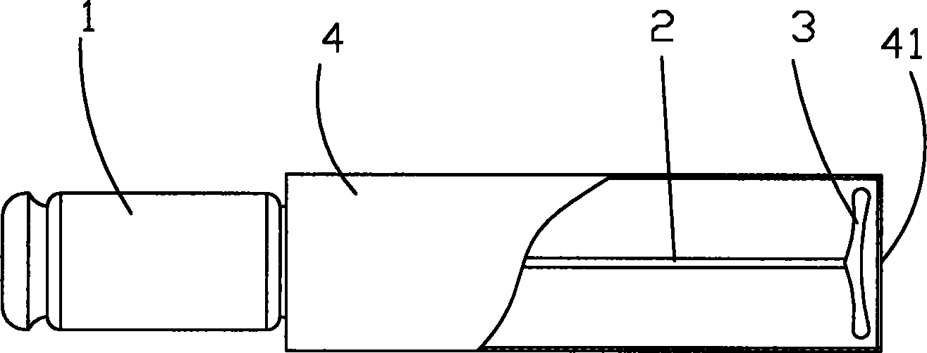
[0015] See figure 1 , a cooling tank stirring device with a shroud, including a motor 1, a rotating shaft 2 fixed on the top of the motor 1, a blade 3 installed on the bottom of the rotating shaft 2, and a shroud 4 surrounding the periphery of the blade 3 , the blade 3 is a propeller blade, which has better stirring performance compared to other blades. The shroud 4 is cylindrical in design, and its bottom is provided with an opening 41. In specific use, the quenching oil 8 passes through the opening 41 The inlet and outlet shroud 4 extends from the blade 3 to the bottom of the motor 1 , and the shroud 4 is arranged parallel to the rotating shaft 2 .

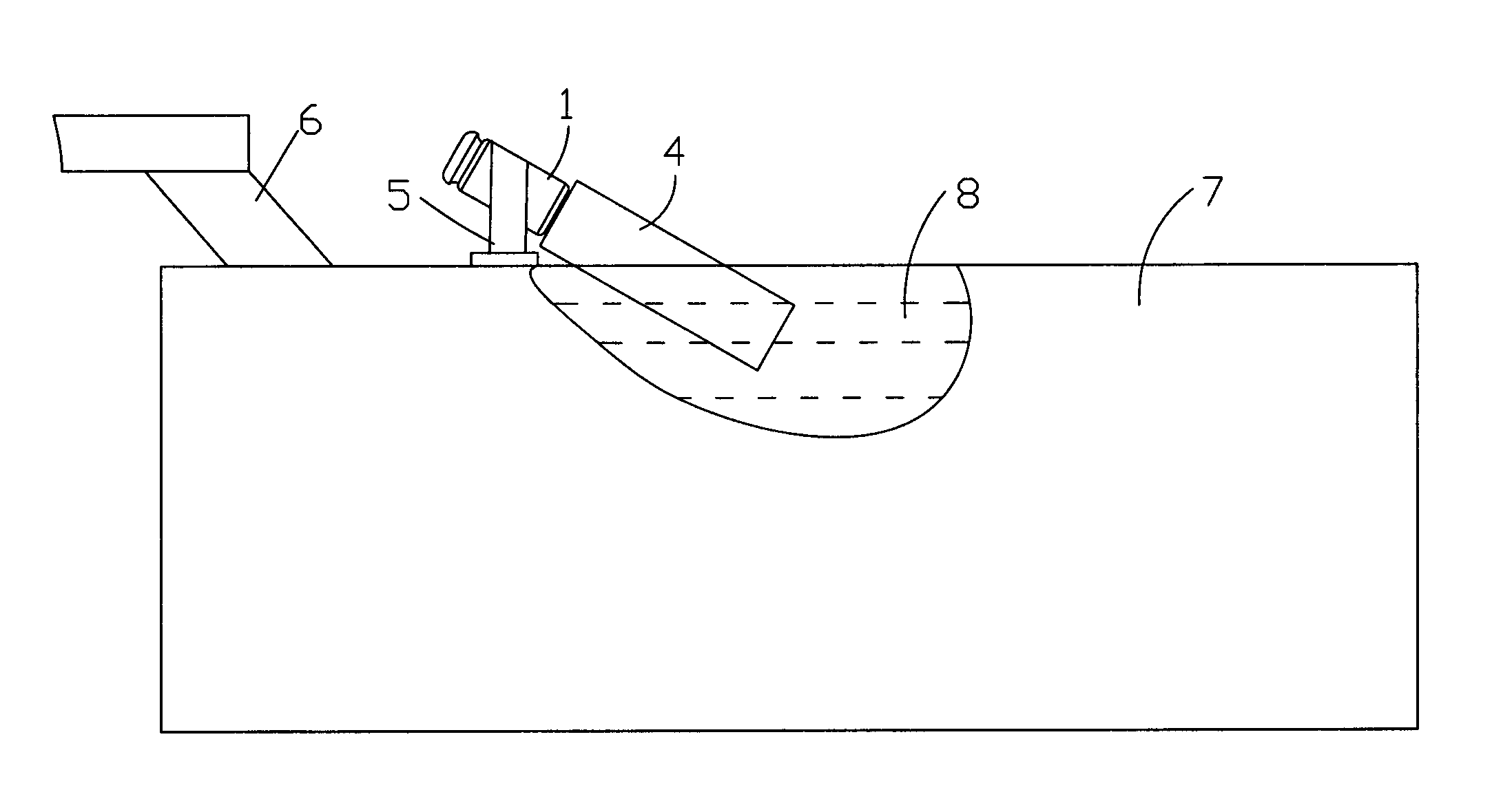
[0016] See figure 2 , the device is arranged in the cooling tank 7, and supported by the support frame 5, in order to achieve the best effect of the device, it can be installed obliquely. During use, ...


PUM


Abstract

The invention relates to a cooling tank stirring device with a diversion cover, and belongs to a quenching chemical device. The cooling tank stirring device comprises a motor, a rotating shaft, a blade and the diversion cover, wherein the top of the rotating shaft is fixed on the motor; the blade is arranged at the bottom of the rotating shaft; and the diversion cover encircles the blade. The device has simple structure; and by arranging the device in a cooling tank, components and temperature of quenching oil in the cooling tank are more uniform, and the quenching performance of a machined metal piece is more uniform.

Description

technical field [0001] The invention relates to a cooling tank stirring device with a flow guide cover, belonging to a quenching treatment mechanical device. Background technique [0002] Many metal processing parts, such as hardware parts, auto parts, tools, etc., need to be quenched to increase their surface hardness, as well as improve their wear resistance and contact strength to meet their respective design requirements. In order to achieve the above goals, quenching furnaces are usually used. . In the existing quenching process, the metal parts to be processed should be quenched with quenching oil in the cooling tank. Generally, the quenching time is relatively long. Over time, the specific components in the quenching oil will sink. In this way, the bottom of the cooling tank The quenching hardness of the processed metal parts may be much higher than that of the processed parts in the upper part of the cooling tank, resulting in uneven quenching properties of the same...

Claims


Application Information

Patent Timeline
IPC IPC(8): C21D1/63
Inventor 宋芬宋国平
Owner 苏州新凌电炉有限公司
Features
  • R&D
  • Intellectual Property
  • Life Sciences
  • Materials
  • Tech Scout
  • Unparalleled Data Quality
  • Higher Quality Content
  • 60% Fewer Hallucinations
Learn More