Device and method for positioning template corner

A positioning device and formwork technology, which is applied in the direction of ship lifting device, formwork/formwork/work frame, formwork/formwork/work frame connectors, etc. It can solve the difficulty in meeting the precision requirements for formwork reinforcement and the inability to form tie rods. Reinforcement and other issues

Active Publication Date: 2012-03-21
GEZHOUBA XINJIANG ENG
View PDF7 Cites 5 Cited by
  • Summary
  • Abstract
  • Description
  • Claims
  • Application Information

AI Technical Summary

Problems solved by technology

In the construction of hydraulic self-elevating formwork, since the opposite side of the outer formwork at the corner (or "T" shape) is in the empty state (no formwork), it

Method used


Image

  • Device and method for positioning template corner
  • Device and method for positioning template corner
  • Device and method for positioning template corner

Examples


Embodiment Construction

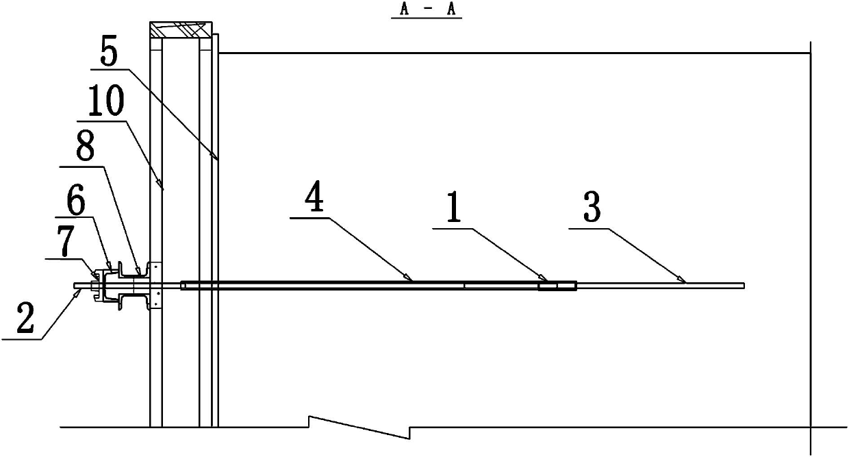
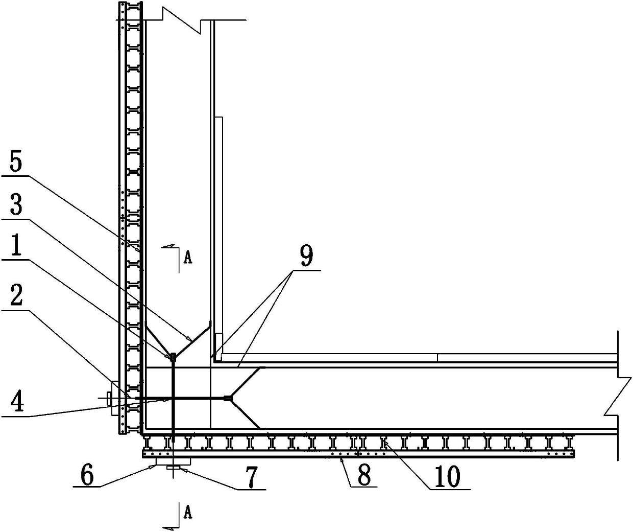
[0024] Such as figure 1 , figure 2 Among them, a formwork corner positioning device, including a formwork 5, the formwork 5 is provided with a longitudinal enclosure 10 and a transverse enclosure 8, a tie screw 2 is installed at the corner of the formwork 5, and one end of the tie screw 2 passes through the liner 6 and the nut 7 are connected with the template 5, and the other end is connected with the weldable sleeve 1; the corner parts mentioned here also include the parts where the braces cannot be pulled against each other in the "T"-shaped parts.

[0025] The weldable sleeve 1 is welded and connected to the steel bar 9 in the warehouse through the brace 3 .

[0026] The weldable sleeve 1 is made of a weldable material with an outer diameter of 24mm and a length of 12-15cm, such as No. 45 steel. The weldable sleeve 1 is internally processed with an internal thread that cooperates with the rod screw 2 .

[0027] The said bracing screw 2 is provided with a casing 4, one e...


PUM


Abstract

The invention discloses a method for positioning a template corner, which comprises a template, wherein a wailing is arranged outside the template; a lashing strip screw is arranged at the position of the template corner; one end of the lashing strip screw is connected with the template through a liner and a nut; the other end of the lashing strip screw is in threaded connection with a weldable sleeve; and the weldable sleeve is welded with steel reinforcing bars through lashing strips. A casing is arranged outside the lashing strip screw; one end of the casing penetrates out of the template; and the other end of the casing is attached to the weldable sleeve. According to the method disclosed by the invention, the weldable sleeve is welded with a general reinforced lashing strip and is also connected with a high-strength screw, so that the requirement of the template lashing strip at the corner (or T-shaped) part on diagonal pulling and reinforcing is met and the reinforced positioning of a hydraulic self-climbing template at the corner (or T-shaped) part can be ensured to meet the requirement of construction quality. The method is especially suitable for reinforcing construction of templates for tower column structural concrete of ship lifter engineering in a hydropower station under the condition that various templates at corner parts cannot form diagonal pull by using the lashing strips.

Description

technical field [0001] The invention relates to a device and method for locating formwork corners in concrete pouring, in particular to a device and method for locating formwork corners. Background technique [0002] In the construction of the ship lift project of the hydropower station, the design precision of the tower column structure concrete is particularly high, and the hydraulic self-elevating formwork is generally used for vertical formwork construction. Because the panel of the hydraulic self-elevating formwork is made of imported Finnish plate material, the price is expensive, and the overall formwork is heavy. There are brace holes for reinforcing the formwork reserved on the panel. If ordinary braces are used to pull the reinforcement formwork, the braces will The strength is far below the requirements, so this set of formwork is equipped with special high-strength manganese steel braces. This special brace cannot be welded with ordinary steel bars, and its price...

Claims


Application Information

Patent Timeline
IPC IPC(8): E02C5/00E02C3/00E04G13/02E04G17/065E04G21/00
CPCE04G17/0654
Inventor 周厚贵戴志清曾明孙昌忠詹剑霞周雄汪文亮黄家权
Owner GEZHOUBA XINJIANG ENG
Why Eureka
Try Eureka