System for controlling hydraulic pressure and flow rate of oil in engine and control method thereof

A technology of engine and engine parameters, which is applied in the direction of engine lubrication, control of lubricant pressure, engine components, etc., can solve the problems of increased hydraulic loss and increased fuel consumption, and achieve the effect of preventing friction loss

Inactive Publication Date: 2012-03-21
HYUNDAI MOTOR CO LTD +1
View PDF8 Cites 6 Cited by
  • Summary
  • Abstract
  • Description
  • Claims
  • Application Information

AI Technical Summary

Problems solved by technology

This means higher oil pump work, increased hydraulic losses at the oil pump, oil cooler, oil filter, and increased oil consumption due to unnecessary supply of oil

Method used


Image

  • System for controlling hydraulic pressure and flow rate of oil in engine and control method thereof
  • System for controlling hydraulic pressure and flow rate of oil in engine and control method thereof
  • System for controlling hydraulic pressure and flow rate of oil in engine and control method thereof

Examples


Embodiment Construction

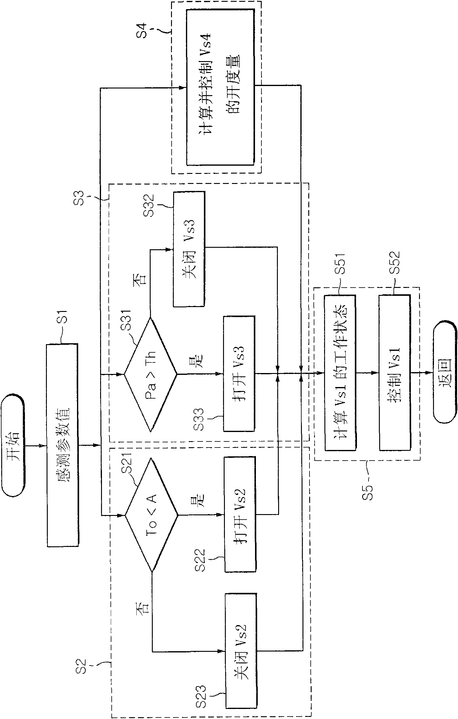
[0023] Reference will now be made in detail to various embodiments of the invention, examples of which are illustrated in the accompanying drawings and described below. While the invention will be described in conjunction with exemplary embodiments, it will be appreciated that present description is not intended to limit the invention to those exemplary embodiments. On the contrary, the invention is intended to cover not only the exemplary embodiments but also various alternatives, modifications, equivalents and others which may be included within the spirit and scope of the invention as defined by the appended claims. implementation.

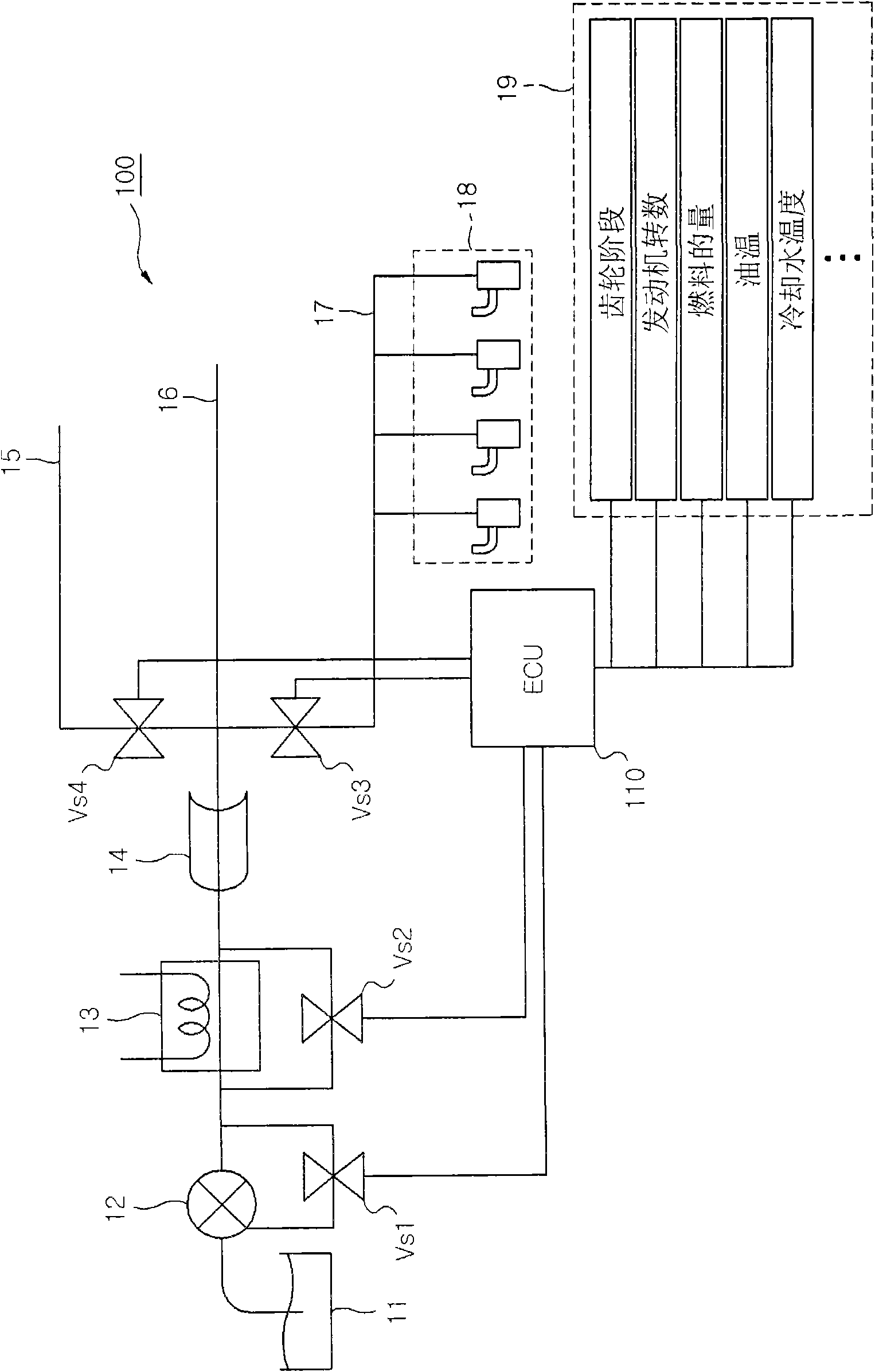
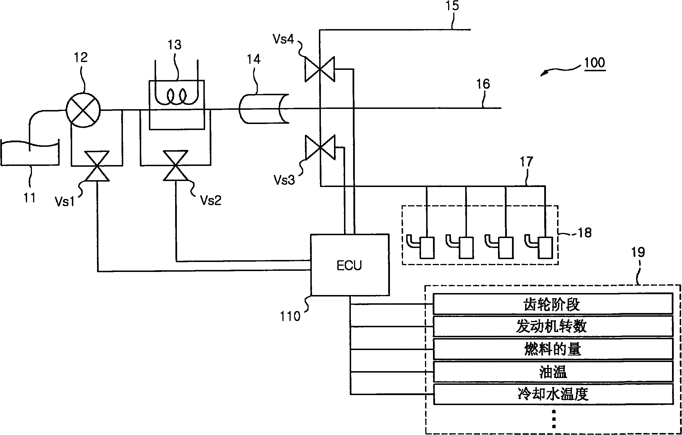
[0024] refer to figure 1 As shown, in a system for supplying oil into an engine, when the engine is started, an oil pump 12 pumps oil from an oil pan 11 connected to an inlet, and discharges oil through an outlet. The oil is delivered to an oil cooler 13 connected to an outlet of the oil pump 12 at a predetermined pressure, and is cooled by ...


PUM


Abstract

A system for controlling hydraulic pressure and flow rate of oil in an engine, may include a first solenoid valve disposed in a channel connecting an inlet and an outlet of an oil pump supplying oil from an oil pan to the engine, and an electronic controller controlling the first solenoid valve on the basis of number of revolution of the engine, load of the engine, and temperature of the oil.

Description

[0001] Cross References to Related Applications [0002] This application claims priority from Korean Patent Application No. 10-2010-0084694 filed on Aug. 31, 2010, the entire contents of which are hereby incorporated by reference for all purposes. technical field [0003] The present invention relates to a system for controlling the hydraulic pressure and flow rate of oil in an engine and a control method thereof, more particularly, the present invention relates to a system for controlling the hydraulic pressure and flow rate of oil in an engine, which depends on And the temperature of the oil to control the opening of the solenoid valve installed in each channel, so that the oil is supplied corresponding to the minimum flow rate required by each gallery (gallery), thereby preventing friction loss caused by hydraulic pressure and unnecessary oil consumption , the present invention also relates to the control method of the system. Background technique [0004] Generally, in...

Claims


Application Information

Patent Timeline
Patent Type & Authority Applications(China)
IPC IPC(8): F01M1/16
CPCF01M5/005F01M1/16F01M1/08
Inventor 郑映录
Owner HYUNDAI MOTOR CO LTD
Why Eureka
Try Eureka