Small-pullout-force optical fiber connector shell and optical fiber connector using same

A technology for optical fiber connectors and housings, which is applied in the field of optical cable connection equipment, can solve problems such as large pull-out force, and achieve the effect of solving large pull-out force and reducing pull-out force

Inactive Publication Date: 2012-03-21
CHINA AVIATION OPTICAL-ELECTRICAL TECH CO LTD
View PDF5 Cites 1 Cited by
  • Summary
  • Abstract
  • Description
  • Claims
  • Application Information

AI Technical Summary

Problems solved by technology

[0003] The purpose of the present invention is to provide a small pulling force optical fiber connector housing to solve the problem of the large pulling force required when the optical fib

Method used


Image

  • Small-pullout-force optical fiber connector shell and optical fiber connector using same
  • Small-pullout-force optical fiber connector shell and optical fiber connector using same
  • Small-pullout-force optical fiber connector shell and optical fiber connector using same

Examples


Embodiment Construction

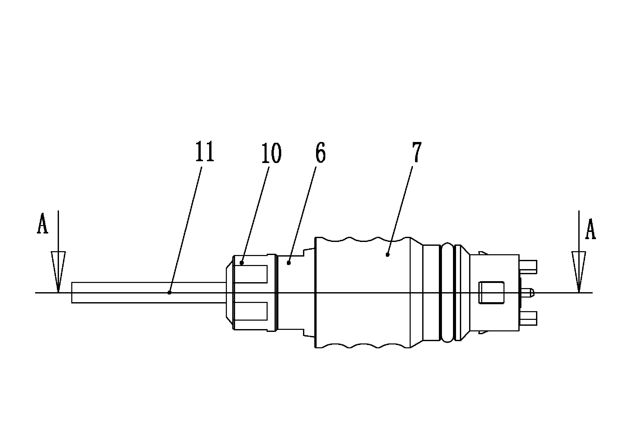
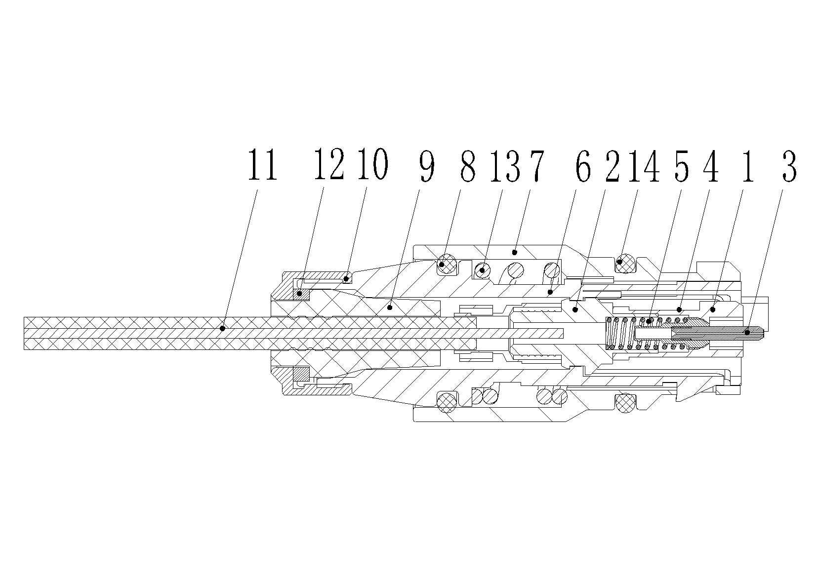
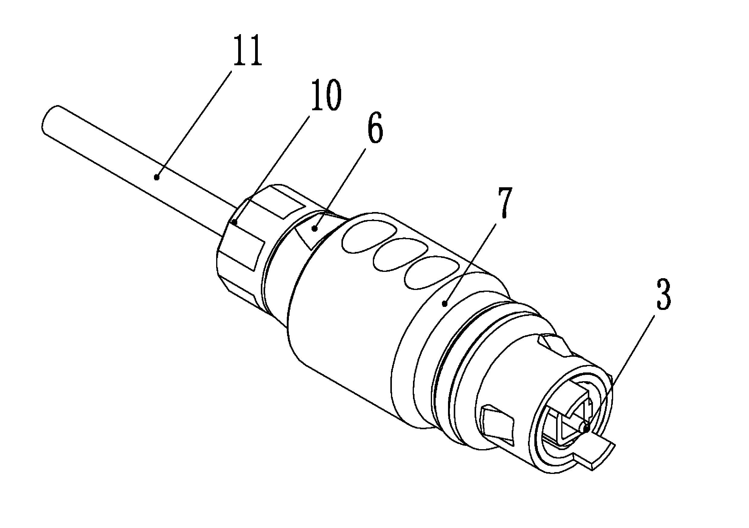
[0032] Embodiment 1 of the fiber optic connector, such as Figure 1-16 As shown, it consists of a housing and a pin assembly inside the housing.

[0033] Pin components (such as Figure 4-8 ) has a pin housing. The pin housing is composed of a front housing 1 and a rear housing 2. The outer contour of the front housing 1 is rectangular and has an inner hole extending axially. The inner hole of the front housing 1 There is a baffle plate 1-1, the baffle plate 1-1 has a through hole through the front and back, and the pin 3 is installed in the through hole along the axial movable guide, the rear end of the pin 3 is provided with a pin seat 4, and the pin seat 4 is arranged on the back end of the pin The front end of the needle seat 4 cooperates with the rear side of the baffle plate 1-1 to stop and limit, and the rear end is provided with a buffer spring 5; the front housing 1 is provided with a front housing hanging hole 1-2 on its circumference, which The through hole in the...


PUM


Abstract

The invention relates to a small-pullout-force optical fiber connector shell and an optical fiber connector using the same. The optical fiber connector shell comprises an outer shell and an inner shell, wherein, the outer shell is provided with a mounting hole for assembling the inner shell, the mounting hole comprises a front-end small-diameter section and a rear-end large-diameter section, and a step surface is formed between the large-diameter section and the small-diameter section; the front end of the inner shell is equipped with an elastic agnail which can contract in a radial direction, and the inner shell axially penetrates into the outer shell from the rear end of the outer shell and then is axially matched with a shell hanging hole arranged on the hole wall of the small-diameter section of the mounting hole in an unidirectional limit manner through the elastic agnail; and a return spring is arranged between the step surface and an outer flange which is arranged on the outer wall surface of the inner shell. By adopting the optical fiber connector shell, fractional stepwise separation between the outer shell and the inner shell is realized when the optical fiber connector is separated from a corresponding adapter, which reduces the pullout force needed in the event that the optical fiber connector for pre-connection is separated from the corresponding adapter, and solves the problem of the large pullout force needed in the event that the optical fiber connector is separated from the corresponding adapter.

Description

technical field [0001] The invention relates to an optical cable connection device, in particular to a housing of a small pulling force optical fiber connector and an optical fiber connector using the housing. Background technique [0002] Compared with traditional connection methods such as fusion splicing, cold splicing or on-site grinding splicing of the traditional optical fiber terminal, the pre-connection technology adopts the optical fiber straight-through method, that is, the optical fiber has no connection point. According to the requirements of customers, the products are customized by the factory, and the grinding process is carried out according to the standard procedure. All technical indicators comply with IEC, TIA and related standards. In this regard, the technical indicators far exceed the connectors ground on site. Among them, the optical fiber connector is an indispensable key component in the pre-connection technology. The general optical fiber connector ...

Claims


Application Information

Patent Timeline
IPC IPC(8): G02B6/38
Inventor 李小卫李卫可
Owner CHINA AVIATION OPTICAL-ELECTRICAL TECH CO LTD
Why Eureka
Try Eureka