Forming method of contact wire
A forming method and contact wire technology, which is applied in the direction of overhead wire, metal wire drawing, manufacturing tools, etc., can solve problems such as insufficient smoothness, time-consuming and labor-intensive polishing, and difficulty in controlling the quality of contact wires.
- Summary
- Abstract
- Description
- Claims
- Application Information
AI Technical Summary
Problems solved by technology
Method used
Image
Examples
Embodiment 1
[0055] Such as figure 1 , image 3 Shown, a kind of forming method of contact wire, comprises the steps:
[0056] S1: Will Copper-chromium-zirconium alloy raw material wire with yield strength greater than 500MPa is loaded into the uncoiler in large coils;
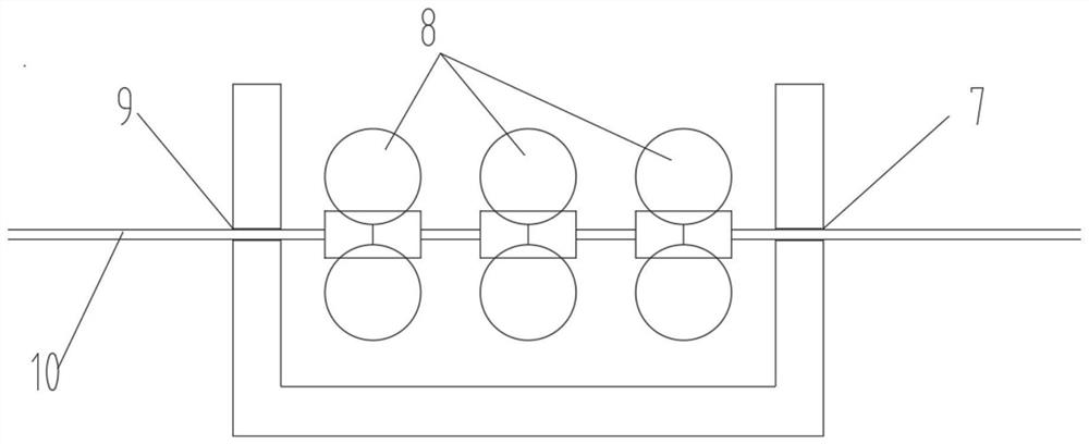
[0057] S2: The raw material wire is straightened and straightened by the straightening device 2 and the straightening puller 3 to obtain a straightened straight rod; S3: The pulled straight rod is pulled by the first puller 5, and the straightened rod passes through the first roller drawing device 4 Feed guide hole 7, after three groups of roller drawing molds in the first roller drawing device 4, lead out through discharge guide hole 9; Pull the straight rod through drawing speed and be three groups namely three groups of 10~50m / min The rolling deformation of the rolling die of the pass is 150mm as required by the TB / T2809-2017 standard 2 Slotted section contact wire for contact wire specifications.
[0058] Such a...
Embodiment 2
[0064] Such as figure 2 , image 3 Shown, a kind of forming method of contact wire, comprises the steps:
[0065] S1: Will Copper-chromium-zirconium alloy raw material wire with yield strength greater than 500MPa is loaded into the uncoiler in large coils;
[0066] S2: The raw material wire is straightened and straightened by the straightening device 2 and the straightening puller 3 to obtain a straightened wire;
[0067] S3: The straight rod is pulled by the first puller 5, the straight rod passes through the feeding guide hole 7 of the first roller drawing device 4, and then passes through the three groups of rollers in the first roller drawing device 4 to draw the mold, Exported through the discharge guide hole 9;
[0068] Pulled by the second pulling plate 5', the straight rod passes through the feed guide hole of the second roller drawing device 4', and then passes through the three sets of rollers in the second roller drawing device to draw the mold, and then passe...
Embodiment 3
[0072] Between the adjacent rollers in embodiment 1, an angle of 120 degrees can be formed with each other, such as Figure 6 , Figure 7 shown. Other setting methods are the same as those in Embodiment 1, and will not be repeated here.
[0073] The obtained copper-chromium-zirconium alloy contact wire 150mm of embodiment 1 2 (CTCZ120) and the obtained copper-chromium-zirconium alloy contact wire 120mm of embodiment 2 2 (CTCZ150) The test data of mechanical properties, electrical properties, external dimensions, etc. are as follows:
[0074]
[0075]
[0076] illustrate:
[0077] 1. Description of A, B, C, D, H, G symbols:
[0078] Such as Figure 8 As shown, A-section diameter (height); B-section width; C-head width; D-(groove) bottom spacing;
[0079] H-upper bevel; G-lower bevel.
[0080] 2. Vibration test: amplitude 35mm, frequency 3Hz, sine wave, applied test tension 31.5kN;
[0081] 3. Fatigue test: dynamic test tension 30±9kN, frequency 3Hz, sine wave;
...
PUM
 Abstract
Description
Claims
Application Information
 - R&D
- Intellectual Property
- Life Sciences
- Materials
- Tech Scout
- Unparalleled Data Quality
- Higher Quality Content
- 60% Fewer Hallucinations
Browse by: Latest US Patents, China's latest patents, Technical Efficacy Thesaurus, Application Domain, Technology Topic, Popular Technical Reports.
© 2025 PatSnap. All rights reserved.Legal|Privacy policy|Modern Slavery Act Transparency Statement|Sitemap|About US| Contact US: help@patsnap.com


