
Solid state storage device and data control method thereof

A solid-state storage and data control technology, applied in static memory, electrical digital data processing, information storage, etc., can solve problems such as data disappearance

Inactive Publication Date: 2012-03-21
LITE ON IT
View PDF3 Cites 13 Cited by
  • Summary
  • Abstract
  • Description
  • Claims
  • Application Information

AI Technical Summary

Problems solved by technology

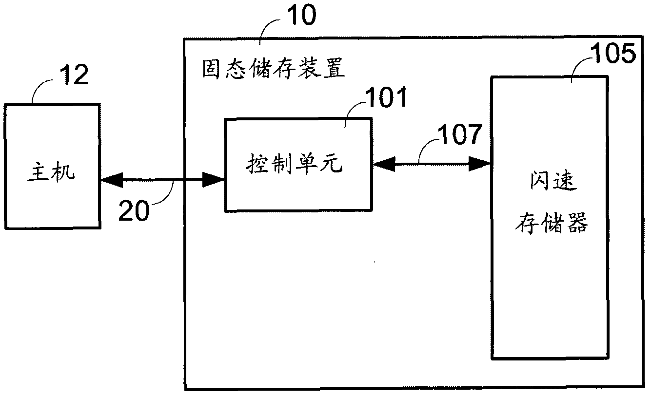
Therefore, the data recorded in these memory cells will probably disappear after a period of time after data writing is completed in the current flash memory 105.

Method used


Image

  • Solid state storage device and data control method thereof
  • Solid state storage device and data control method thereof
  • Solid state storage device and data control method thereof

Examples


Embodiment Construction

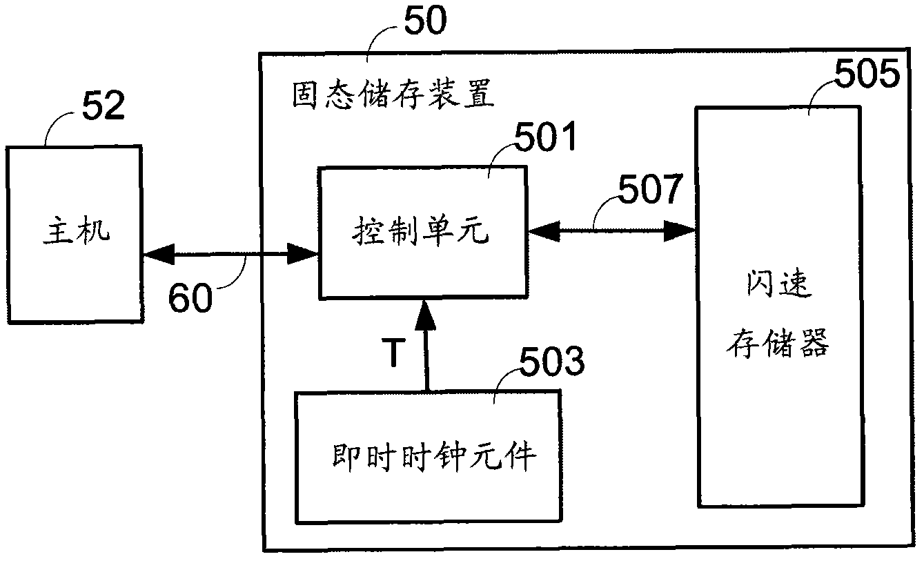
[0028] Please refer to figure 2 , which shows a schematic diagram of the solid state storage device of the present invention. The solid state storage device 50 includes a control unit 501 and a flash memory 505 . An internal bus 507 is used to access data between the control unit 501 and the flash memory 505 , and an external bus 60 is used to transmit instructions and data between the control unit 501 and the host (host) 52 . Furthermore, the present invention adds a real time clock (RTC) component 503 in the solid state storage device, and the real time clock component 503 can output a time signal T to the control unit 501 . Furthermore, the external bus 60 can be a USB bus, an IEEE 1394 bus, a SATA bus, and so on.

[0029] According to the embodiment of the present invention, the control unit 501 establishes a time parameter, which is the time signal T generated by the real-time clock component 503, which includes time information of year, month, day, hour, minute and se...


PUM


Abstract

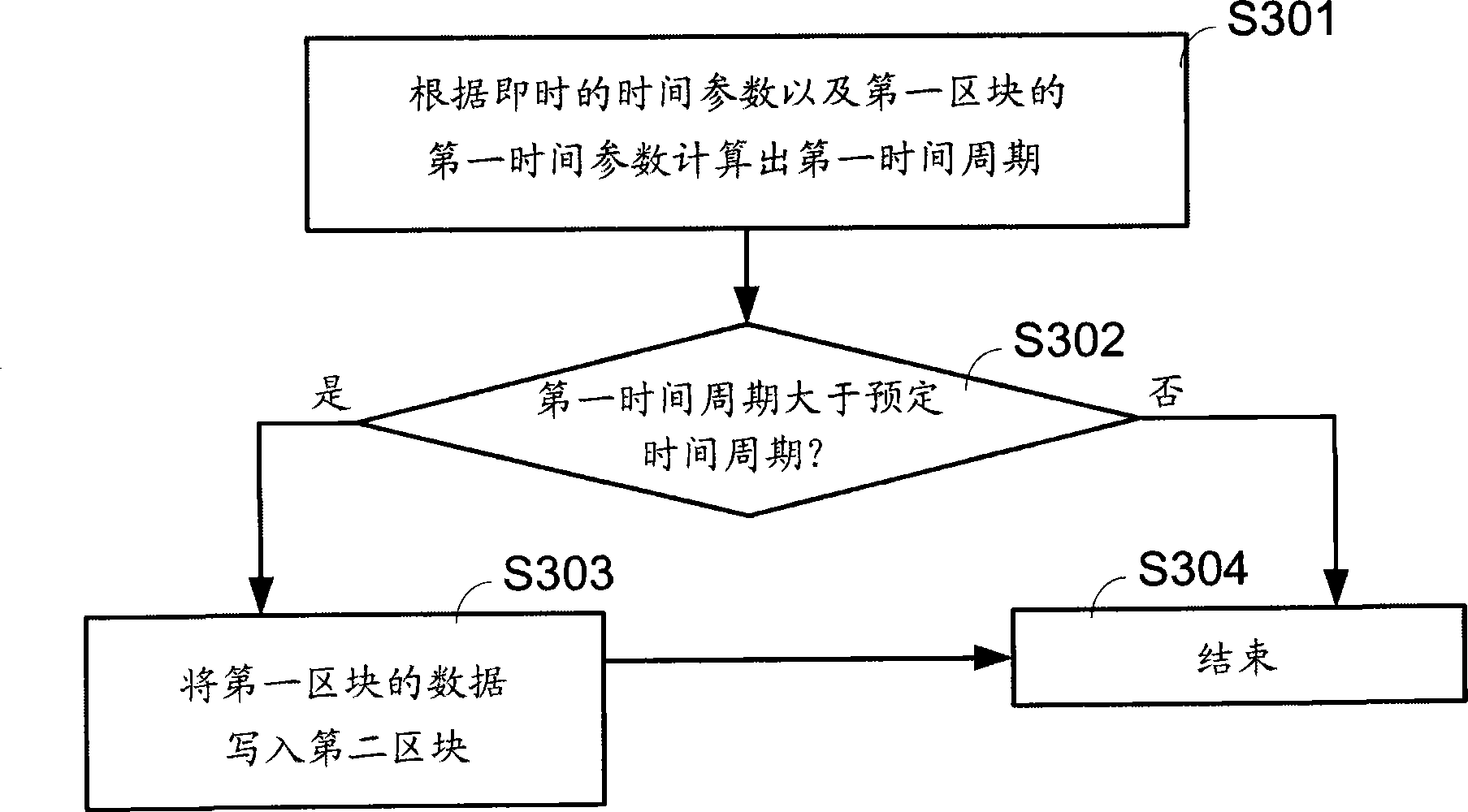
The invention discloses a solid state storage device and a data control method thereof. The solid state storage device comprises a flash memory and a control unit, wherein the flash memory comprises a plurality of blocks; each block comprises a plurality of pages; the control unit is connected to the flash memory; and when the control unit erases data or writes the data into the blocks, the control unit provides a time parameter for each block, so that the control unit can execute a data loss protection operation, an average erasing block operation or a garbage collection operation according to the time parameters.

Description

technical field [0001] The present invention relates to a solid state storage device, in particular to a data control method of the solid state storage device. Background technique [0002] As we all know, solid state storage device (Solid State Drive, SSD) uses NAND flash memory (NAND flash memory) as the main storage element, and this kind of flash memory is a kind of non-volatile (non-volatile) memory element. That is, after data is written into the flash memory, once the system power is turned off, the data remains in the flash memory. [0003] Please refer to figure 1 , which shows a schematic diagram of a conventional solid-state storage device. The solid state storage device 10 includes a control unit 101 and a flash memory 105 . An internal bus 107 is used to access data between the control unit 101 and the flash memory 105 , and an external bus 20 is used to transmit instructions and data between the control unit 101 and the host (host) 12 . Wherein, the extern...

Claims


Application Information

Patent Timeline
Patent Type & Authority Applications(China)
IPC IPC(8): G11C7/10G06F12/06
CPCG06F2212/7205G11C16/349G06F12/0246G06F2212/7211
Inventor 蔡松峰徐正煜陈凌风
Owner LITE ON IT
Learn More