OFDM receiving apparatus
A receiving device and reception quality technology, which is applied in the field of interception window control, can solve the problems that the reference position of the FFT window cannot be obtained, the FFT window cannot be controlled, and the FFT window cannot be controlled at the position with the best reception quality.
- Summary
- Abstract
- Description
- Claims
- Application Information
AI Technical Summary
Problems solved by technology
Method used
Image

Examples
no. 1 approach
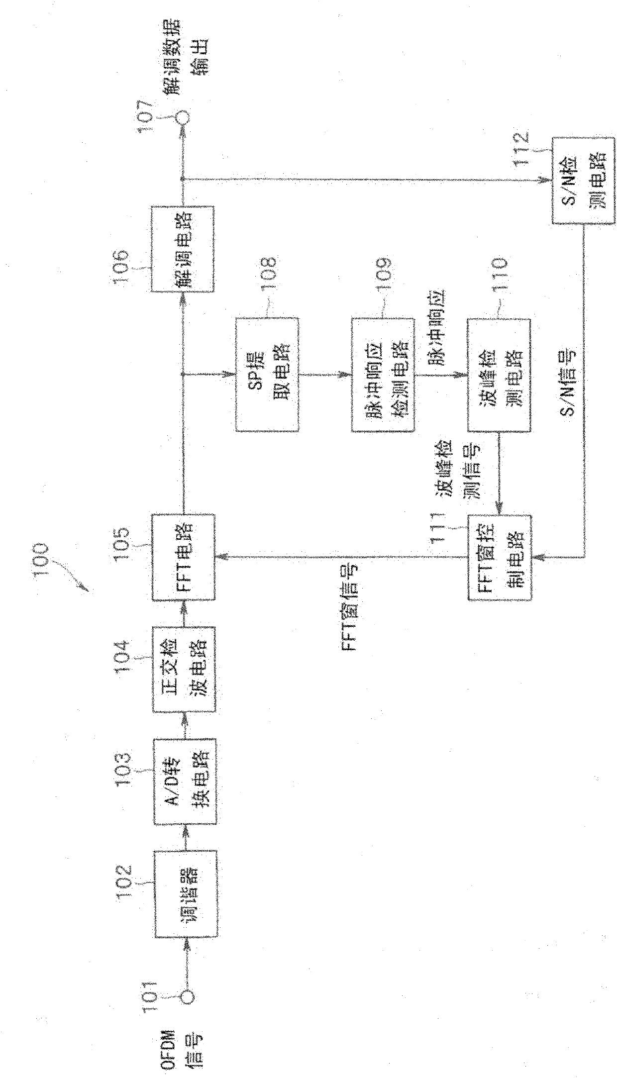
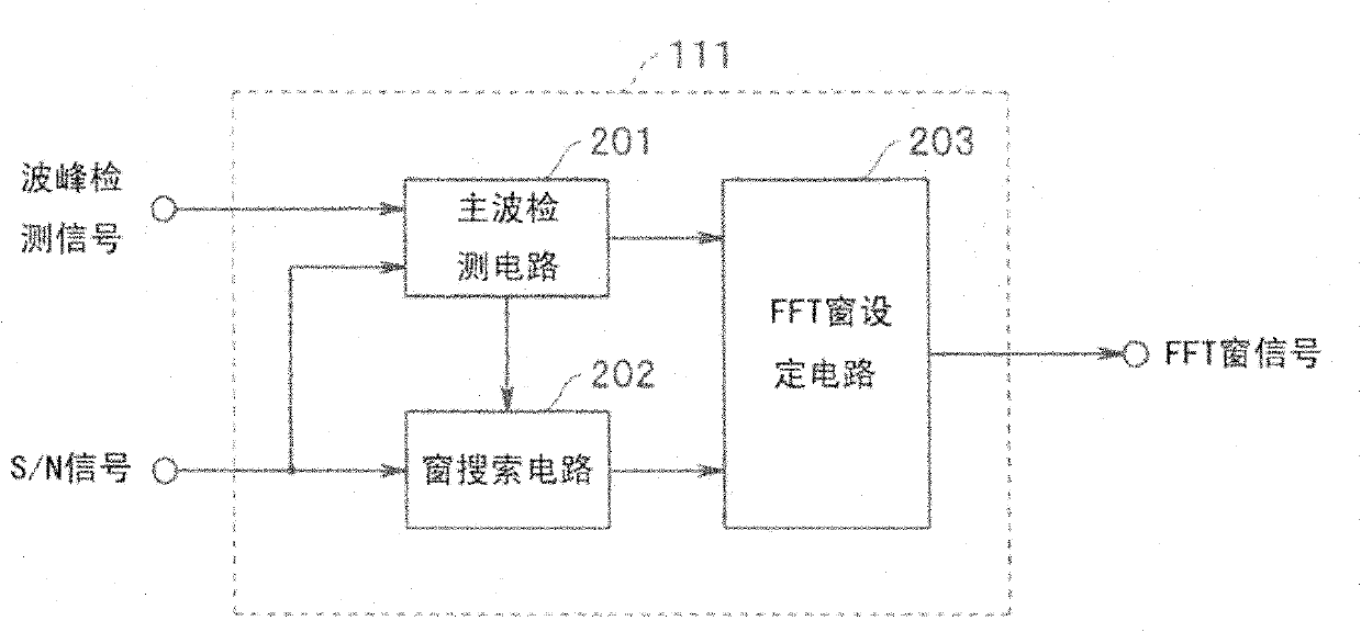
[0021] figure 1 It is a block diagram showing the configuration of the OFDM receiving apparatus according to the first embodiment. exist figure 1 Among them, the OFDM receiving device 100 includes an input terminal 101 for an OFDM modulated signal, a tuner 102, an A / D conversion circuit 103, a quadrature detection circuit 104, an FFT circuit 105 as a Fourier transform unit, and a demodulation circuit as a data demodulation unit. 106, the output terminal 107 of the demodulated signal, the SP extraction circuit 108 as the pilot extraction unit, the impulse response detection circuit 109 as the impulse response detection unit, the peak detection circuit 110 as the peak detection unit, the FFT window control circuit 111, and S / N detection circuit 112 as reception quality detection means.
[0022] The OFDM receiving device 100 is a receiving device that receives OFDM signals including SP signals that are pilot signals that are periodically arranged in the frequency direction and ...
no. 2 approach
[0051] Figure 7 An OFDM reception device according to the second embodiment is shown.
[0052] exist Figure 7 Among them, the OFDM receiver 100A has an input terminal 101 for an OFDM modulated signal, a tuner 102, an A / D conversion circuit 103, a quadrature detection circuit 104, an FFT circuit 105, a demodulation circuit 106, an output terminal 107 for a demodulated signal, and an SP Extraction circuit 108, impulse response detection circuit 109A, peak detection circuit 110, FFT window control circuit 111, and S / N detection circuit 112A.
[0053] The structural difference from the first embodiment lies in the impulse response detection circuit 109A and the S / N detection circuit 112A. In the first embodiment, the S / N detection is performed based on the output of the demodulation circuit 106, but in the second embodiment, the S / N detection is performed based on the output of the impulse response detection circuit 109A. Additionally, with figure 1 The same reference numera...
PUM
 Abstract
Description
Claims
Application Information
 - R&D
- Intellectual Property
- Life Sciences
- Materials
- Tech Scout
- Unparalleled Data Quality
- Higher Quality Content
- 60% Fewer Hallucinations
Browse by: Latest US Patents, China's latest patents, Technical Efficacy Thesaurus, Application Domain, Technology Topic, Popular Technical Reports.
© 2025 PatSnap. All rights reserved.Legal|Privacy policy|Modern Slavery Act Transparency Statement|Sitemap|About US| Contact US: help@patsnap.com