Electrode geometry of a galvanic cell

A primary battery and electrode technology, which is applied in the field of primary batteries, can solve problems such as component or environmental damage, and achieve the effects of increasing burden, improving safety, and improving operation safety

Inactive Publication Date: 2012-03-21
LI TEC BATTERY
View PDF4 Cites 3 Cited by
  • Summary
  • Abstract
  • Description
  • Claims
  • Application Information

AI Technical Summary

Problems solved by technology

[0002] Lithium-ion batteries are known from the prior art, the primary cells of which can cause damage to other components of the battery or to the environment in particular due to mechanical damage

Method used


Image

  • Electrode geometry of a galvanic cell
  • Electrode geometry of a galvanic cell
  • Electrode geometry of a galvanic cell

Examples


Embodiment Construction

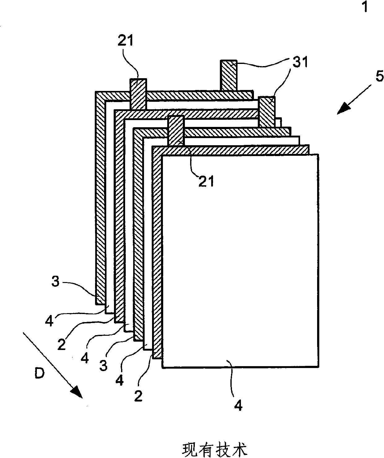
[0051] figure 1 The structure of a galvanic cell 1 according to the prior art is shown. This galvanic cell 1 comprises a plurality of anode electrodes 2 , cathode electrodes 3 and separators 4 which form planar rectangular stacked sheets and are alternately arranged or stacked to form an electrode stack 5 . The stacking direction is given by arrow D.

[0052] Different arrangement sequences for stacking sheets are known from the prior art. The electrodes 2 and 3 are provided with contact elements 21 and 31 which are formed as contact flags and protrude from the electrode stack 5 . Electrode feedthroughs or conductors, not shown, connect contact elements 21 and 31 of a plurality of identical electrodes 2 or 3 to each other. This electrode penetrating part is used for introducing charging current and / or deriving usage current. The housing for the electrode stack 5 is not shown.

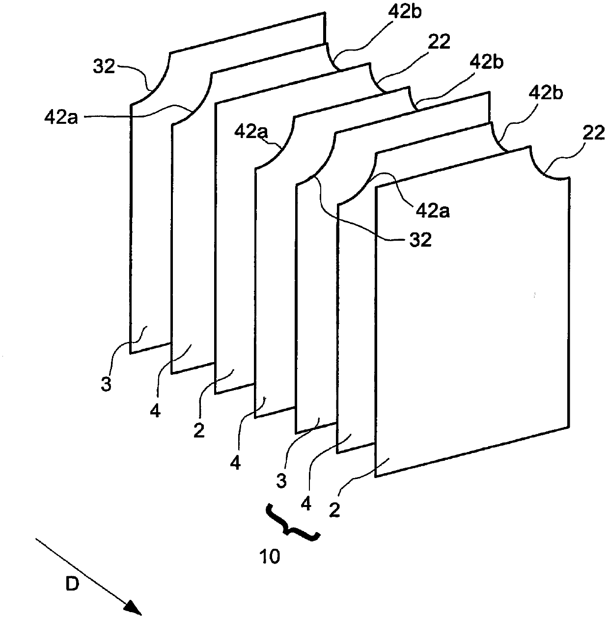
[0053] figure 2 The arrangement of electrodes 2 and 3 and separator 4 according to a first em...


PUM

PropertyMeasurementUnit
diameteraaaaaaaaaa

Abstract

The invention relates to a galvanic cell (1, 10) which comprises an electrode stack (5). Said stack comprises at least one especially flat anode electrode (2), at least one especially flat cathode electrode (3), and at least one especially flat separator (4) which is interposed between said electrodes (3, 4). The invention is characterized in that the outer contour of the separator (4) has at least one cut-out section (42a, 42b) which is offset inwards with respect to said outer contour.

Description

technical field [0001] The invention relates to a galvanic cell according to the preamble of claim 1 . The invention is used together with lithium-ion batteries for powering motor vehicle drives. It should be pointed out that the invention can also be used independently of the chemical properties of the galvanic cells, the type of construction or the type of drive being supplied. Background technique [0002] Lithium-ion batteries are known from the prior art, the primary cells of which can cause damage to other components of the battery or to the environment, in particular due to mechanical damage. For example, chemicals may leak from the battery. Contents of the invention [0003] The object of the invention is to construct a galvanic cell reliably. [0004] This object is achieved by a galvanic cell with the features of claim 1 . This object is furthermore achieved by a galvanic cell with the features of the co-claims. Preferred and advantageous refinements are the...

Claims


Application Information

Patent Timeline
Patent Type & Authority Applications(China)
IPC IPC(8): H01M2/02H01M2/18H01M2/26H01M2/24H01M50/463H01M50/529H01M50/55H01M50/553
CPCH01M2/266H01M10/0525H01M2/24H01M2/18H01M2/021Y02E60/10H01M50/463H01M50/529Y02P70/50H01M50/553H01M50/55H01M50/531H01M50/54H01M50/543H01M50/20
Inventor 蒂姆·舍费尔克里斯丁·容克
Owner LI TEC BATTERY
Why Eureka
Try Eureka