
Vehicle speed limiting system and control method thereof

A technology of vehicle speed limitation and control method, which is applied in the direction of control/regulation system, speed/acceleration control, control device, etc., which can solve problems such as high cost, reduced vehicle speed, complex system, etc., and achieve low cost, ensure driving safety, and simple system Effect

Active Publication Date: 2012-03-28
CHERY AUTOMOBILE CO LTD
View PDF4 Cites 13 Cited by
  • Summary
  • Abstract
  • Description
  • Claims
  • Application Information

AI Technical Summary

Problems solved by technology

The purpose of realizing the speed limit is to reduce car accidents, provide safer driving technology, and effectively reduce the probability of car accidents and the losses caused; the current speed limit and alarm scheme implemented on the car uses automatic identification of speed limit signs to warn and The system is complex and costly to remind the user of the speeding situation; at present, the road speed limit symbol recognition system is mostly used to detect whether the vehicle is speeding, and to provide the driver with speeding alarm information while taking speed limit measures to reduce the speed of the vehicle

Method used


Image

  • Vehicle speed limiting system and control method thereof
  • Vehicle speed limiting system and control method thereof
  • Vehicle speed limiting system and control method thereof

Examples


Embodiment Construction

[0024] The present invention will be described in detail below according to the accompanying drawings, which is a preferred embodiment among various implementations of the present invention.

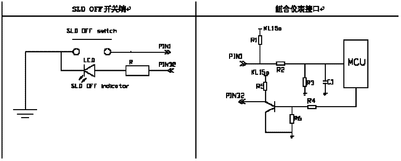
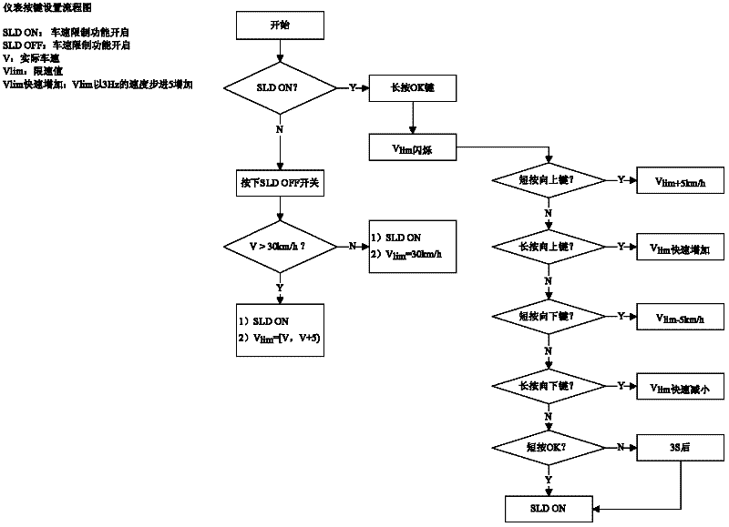
[0025] The present invention adopts the adjustable vehicle speed alarm setting input to the combination instrument, and at the same time, the combination instrument inputs the warning vehicle speed value to the ECU, the ECU executes the vehicle speed limit function, and the combination instrument performs the vehicle speed alarm prompt function according to the execution state of the ECU;

[0026] 1. The combination instrument integrates the speed limit setting function, has the function of speed limit value adjustment and speed limit sound and light alarm function;

[0027] The combined instrument is designed with menu buttons, and the user can input the required speed limit through the LCD menu. After the combined instrument judges according to the alarm logic, if sound and light alarm ...


PUM


Abstract

The invention relates to a vehicle speed limiting system, which comprises a combined instrument, an electric control unit (ECU) and a speed-limiting shielding switch, wherein a vehicle speed alarming device is arranged inside the combined instrument, the vehicle speed alarming device is communicated and connected to the ECU through a controller area network (CAN) bus and transmits and inputs an alarmed vehicle speed value to the ECU, the ECU is connected to a car engine and is used for controlling and executing the limitation of a vehicle speed, and the combined instrument issues a vehicle speed alarming prompting according to an execution state of the ECU.

Description

technical field [0001] The invention relates to a vehicle speed limiting system and a control method thereof. Background technique [0002] Speeding is the real cause of most road traffic accidents. The purpose of realizing the speed limit is to reduce car accidents, provide safer driving technology, and effectively reduce the probability of car accidents and the losses caused; the current speed limit and alarm scheme implemented on the car uses automatic identification of speed limit signs to warn and The system is complex and costly to remind the user of the speeding situation; at present, the road speed limit symbol recognition system is mostly used to detect whether the vehicle is speeding, and to provide the driver with speeding alarm information while taking speed limit measures to reduce the speed of the vehicle. Contents of the invention [0003] The purpose of the present invention is to realize the adjustable vehicle speed limit value function and the active spe...

Claims


Application Information

Patent Timeline
Patent Type & Authority Applications(China)
IPC IPC(8): B60K31/00B60Q5/00
Inventor 朱军平杨宁周定华
Owner CHERY AUTOMOBILE CO LTD
Learn More