Wire reeling, unreeling and arranging device with multiple connected trays

A cable arrangement device and concatenated technology, which is applied in the directions of transportation and packaging, delivery of filamentous materials, thin material processing, etc., can solve the problem of limited height and distance of cable arrangement, limited loading capacity, large floor space, etc. problems, to achieve the effect of eliminating cable stress concentration, avoiding cross crimping, and reducing the number of joints

Active Publication Date: 2012-04-04
亨通海洋工程有限公司
View PDF6 Cites 8 Cited by
  • Summary
  • Abstract
  • Description
  • Claims
  • Application Information

AI Technical Summary

Problems solved by technology

Not only is the loading capacity extremely limited, but also the functions of the take-up frame and the pay-off frame cannot be interchanged. The main disadvantages are:
[0004] 1) The take-up rack is active, it can only take up the wire but not pay it off, otherwise the pay-off rack can only pay off the wire but not take it up; 2) Each set of production equipment needs to be equipped with a passive pay-off rack and an active wire take-up rack , the take-up and release racks of each set of equipment cannot be used uniformly, and occupy a large space; 3) The gantry-type take-up and pay-off racks can currently place a maximum of 5000×2500×2300 (outer diameter of the plate × inn

Method used


Image

  • Wire reeling, unreeling and arranging device with multiple connected trays
  • Wire reeling, unreeling and arranging device with multiple connected trays
  • Wire reeling, unreeling and arranging device with multiple connected trays

Examples


Example Embodiment

[0020] Example 1

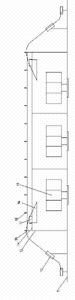
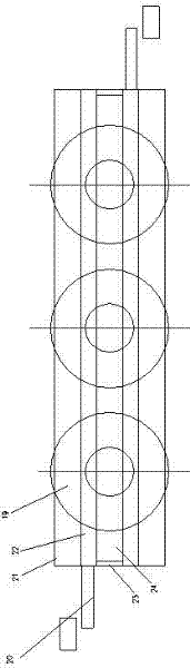
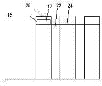
[0021] A multi-connected tray receiving, placing and arranging device, comprising a base 11, a traction device 13, a column 12, a platform 14, a mobile trolley 17, an automatic cable arranging device 18 and a tray 19, the platform 14 is fixed on the column 12 On the base 11, a tray 19 for storing cables is arranged under the platform 14. The number of trays 19 is equal to two. There is a through wire slot 24 above the platform 14. The wire slot is located on the center line of the platform and is connected to a plurality of trays 19 The lines at the center are parallel, the platform 14 is also provided with a mobile trolley 17 which can move on the platform 14, and the mobile trolley 17 is provided with an automatic cable arranging device 18 for arranging the cables. It includes a foot joint 26, a screw rod lifting mechanism 27, a cable arm 29, and an automatic wire-arranging bogie 30. The screw rod lifting mechanism 27 is fixed on the mobile trolley through th...

Example Embodiment

[0024] Example 2

[0025] A multi-connected tray receiving, placing and arranging device, comprising a base 11, a traction device 13, a column 12, a platform 14, a mobile trolley 17, an automatic cable arranging device 18 and a tray 19, the platform 14 is fixed on the column 12 On the base 11, a tray 19 for storing cables is provided under the platform 14. The number of trays 19 is equal to three. A through-line slot 24 is opened above the platform 14. The cable-passing slot is located on the center line of the platform and is connected to a plurality of trays 19 The lines at the center are parallel, the platform 14 is also provided with a mobile trolley 17 which can move on the platform 14, and the mobile trolley 17 is provided with an automatic cable arranging device 18 for arranging the cables. It includes a foot joint 26, a screw rod lifting mechanism 27, a cable arm 29, and an automatic wire-arranging bogie 30. The screw rod lifting mechanism 27 is fixed on the mobile trolle...


PUM


Abstract

The invention discloses a wire reeling, unreeling and arranging device with multiple connected trays. The wire reeling, unreeling and arranging device comprises a base, a traction device, an upright post, a platform, a moving trolley, an automatic wire arranging device and trays. The platform is fixed on the base through the upright post. The trays for storing cables are arranged below the platform. The number of the trays is greater than or equal to two. A through wire passing groove is formed above the platform. The wire passing groove is positioned on a center line of the platform and is parallel to the connecting line of the centers of a plurality of trays. The moving trolley is aloes arranged on the platform and can move on the platform. The automatic wire arranging device for arranging a wire is arranged on the moving trolley. The traction device for conveying the cables is also fixed on the base through the upright post. In the device, a plurality of trays are arranged together in a centralized manner, not only can be used for reeling the cables, but also can be used for unreeling the cables; the number of the trays or portal frames can be reduced by 50 percent; the effects of reeling and unreeling a plurality of cables are realized; and the cost is reduced.

Description

technical field [0001] The invention belongs to the technical field of high-voltage and ultra-high-voltage large-length submarine cables, in particular to a device for collecting, releasing and arranging cables of multiple trays. Background technique [0002] So far, in the entire field of cable production, including high-voltage and ultra-high-voltage submarine cables, wire reels are used to take up and pay off the wires, and the take-up and pay-off racks are of the gantry walking type. [0003] This type of take-up and pay-off device is mainly composed of a lower casing, a column, a tensioning wheel, and a thimble. Not only is the loading capacity extremely limited, but also the functions of the take-up frame and the pay-off frame cannot be interchanged. The main disadvantages are: [0004] 1) The take-up rack is active, it can only take up the wire but not pay it off, otherwise the pay-off rack can only pay off the wire but not take it up; 2) Each set of production equip...

Claims


Application Information

Patent Timeline
IPC IPC(8): B65H54/10B65H54/28B65H49/00
Inventor 王逢春张磊周厚强许勇君施伟明侯家修韩小军
Owner 亨通海洋工程有限公司
Why Eureka
Try Eureka