Remote control electric rolling door direct-current motor control circuit with automatic locking function
An automatic locking, DC motor technology, applied in the field of rolling shutter door control, can solve problems such as inability to guarantee safety, and achieve the effect of guaranteed safety
- Summary
- Abstract
- Description
- Claims
- Application Information
AI Technical Summary
Problems solved by technology
Method used
Image

Examples
Embodiment 1
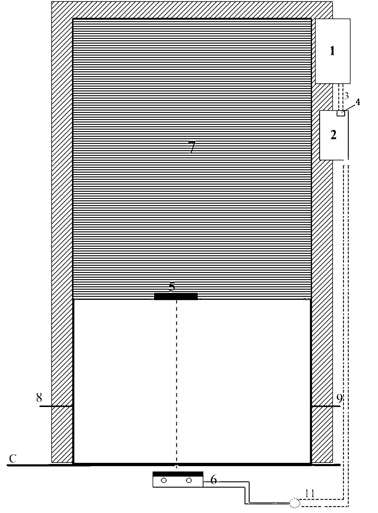
[0022] Embodiment one: see figure 1 , image 3 , Figure 4 and Figure 5 , the electromagnetic lock is fixed on the ground, and the lower edge of the rolling shutter door is fixed with an iron plate 5 (or an electric mortise lock 19 fixed in the middle and lower part of the door frame close to the ground, and at the same time, there is a slot 18 for matching with the electric mortise lock on the corresponding position on the door panel), The rolling door machine is installed on one side of the reel and closed, and the control chip is installed near the motor or hidden in the box near the wall. The control line of the electromagnetic lock (or electric mortise lock) is connected to the output terminal of the control chip U1 after being connected through the PNP Darlington tube Q1. At the same time, the limit output line of the DC motor is connected to the limit interface on the controller.
[0023] The rolling door machine of the rolling door of the rolling door machine acti...
Embodiment 2
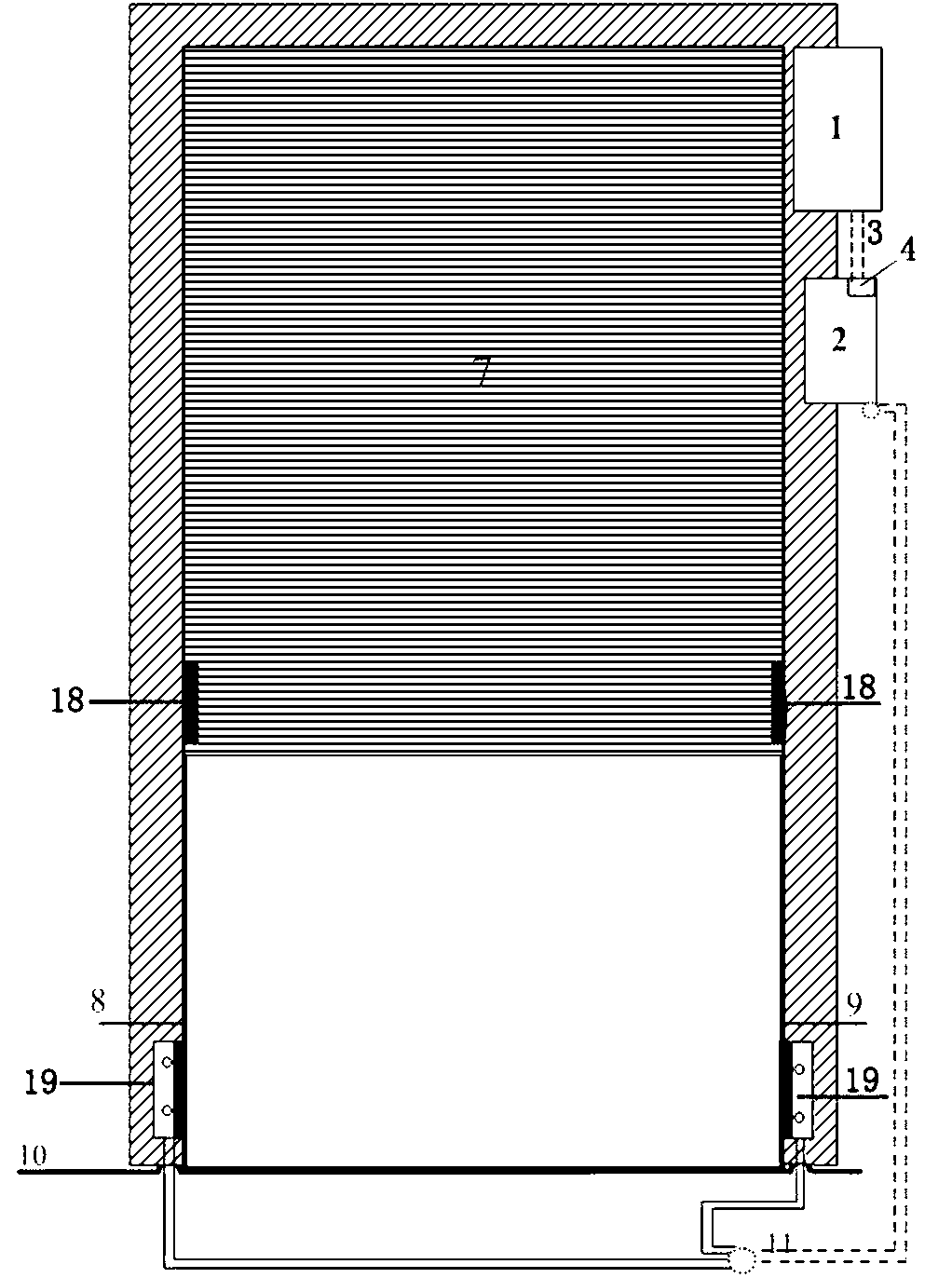
[0038] Embodiment two: see figure 1 , image 3 , Figure 4 and Figure 5 , the electromagnetic lock is fixed on the ground, and the lower edge of the rolling shutter door is fixed with an iron plate 5 (or an electric mortise lock fixed in the middle and lower part of the door frame close to the ground, and at the same time, there is a slot 18 for matching with the electric mortise lock on the corresponding position on the door panel). When the door is closed to the fast bottom, the magnet 3 fixed on the door panel is close to the lower limit probe 4 (the limit probe can be a Hall switch, reed switch, etc.), at this time the lower limit probe sends out a signal to the lower limit, and the controller After detecting the signal of closing the door to the lower limit position, a signal is sent to control the electric mortise lock 19 to be energized to work, and the "bolt" of the electric mortise lock is inserted into the slot 18 in the door panel, and the door is locked, so that...
Embodiment 3
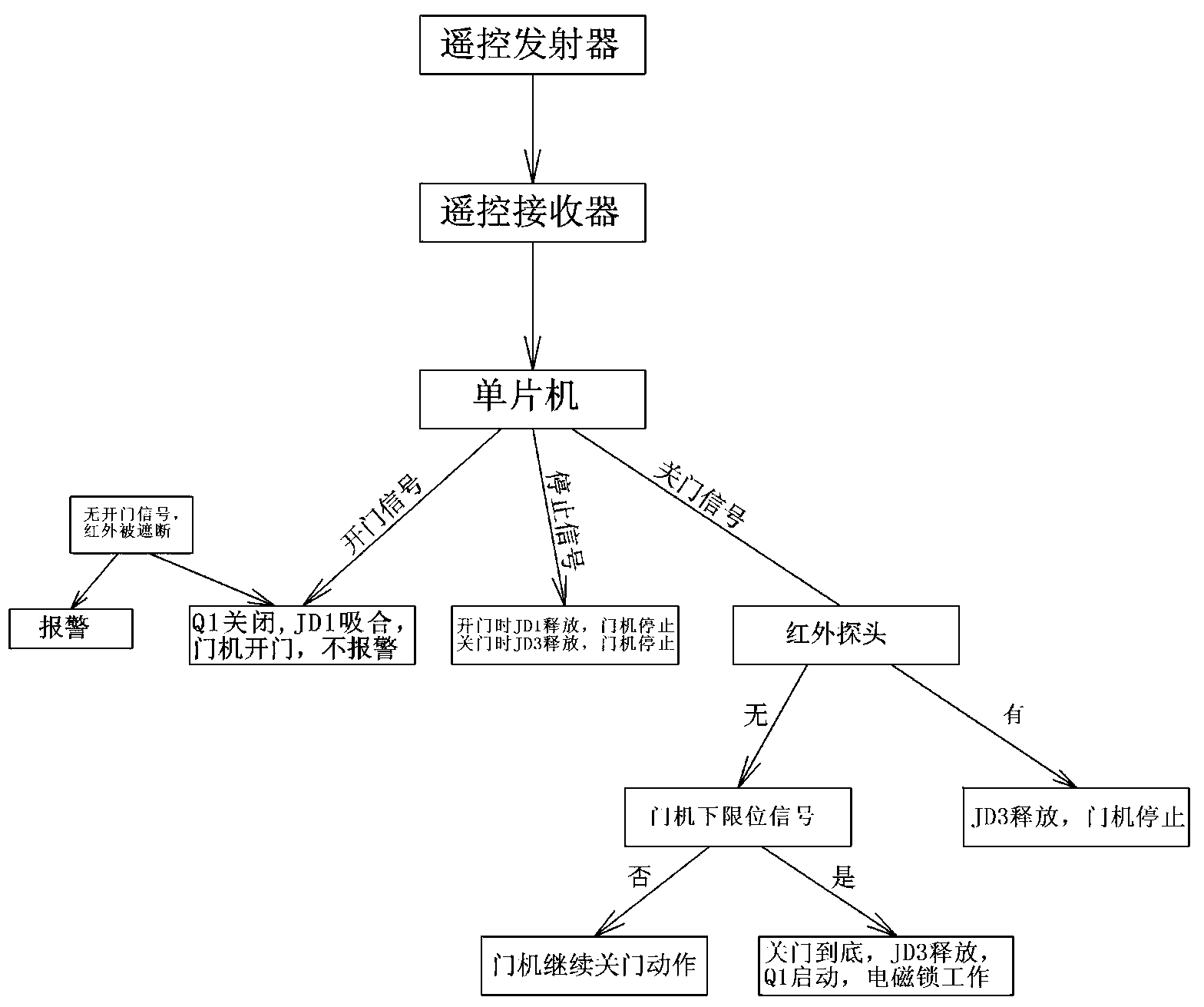
[0039] Embodiment three: see figure 1 , figure 2 and Figure 5 , the content is basically the same as that of Embodiment 1 or 2, and the similarities will not be repeated. The difference is that an infrared sensing module is provided, that is, infrared directing sensors are installed on both sides of the door frame close to the ground, and the infrared sensors on both sides are respectively installed. The signal line of the through-beam sensor is connected with the input end of the control chip. If there is an obstacle under the door during the process of closing the door, the signal from the transmitter of the infrared probe CON4 will be blocked, and the receiving end of the infrared probe will send out a level signal. After the 4th pin of the microcontroller detects the output signal of the infrared probe , will send a high-level signal to pin 14, drive the relay JD2 to pull in, and the door movement will stop.
[0040] Embodiment three: see image 3 , a door opening an...
PUM
 Abstract
Description
Claims
Application Information
 - R&D Engineer
- R&D Manager
- IP Professional
- Industry Leading Data Capabilities
- Powerful AI technology
- Patent DNA Extraction
Browse by: Latest US Patents, China's latest patents, Technical Efficacy Thesaurus, Application Domain, Technology Topic.
© 2024 PatSnap. All rights reserved.Legal|Privacy policy|Modern Slavery Act Transparency Statement|Sitemap