Fault diagnosis technology for mechanical tower
A fault diagnosis and mechanical tower technology, applied in the testing of machines/structural components, measuring vibration, measuring devices, etc., can solve the problems of difficult to put forward design requirements and improvement suggestions, no safety detection device, wind turbine operation resonance damage, etc. question
- Summary
- Abstract
- Description
- Claims
- Application Information
AI Technical Summary
Problems solved by technology
Method used
Image
Examples
Embodiment 1
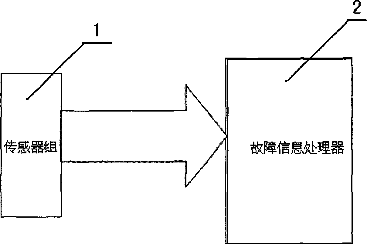
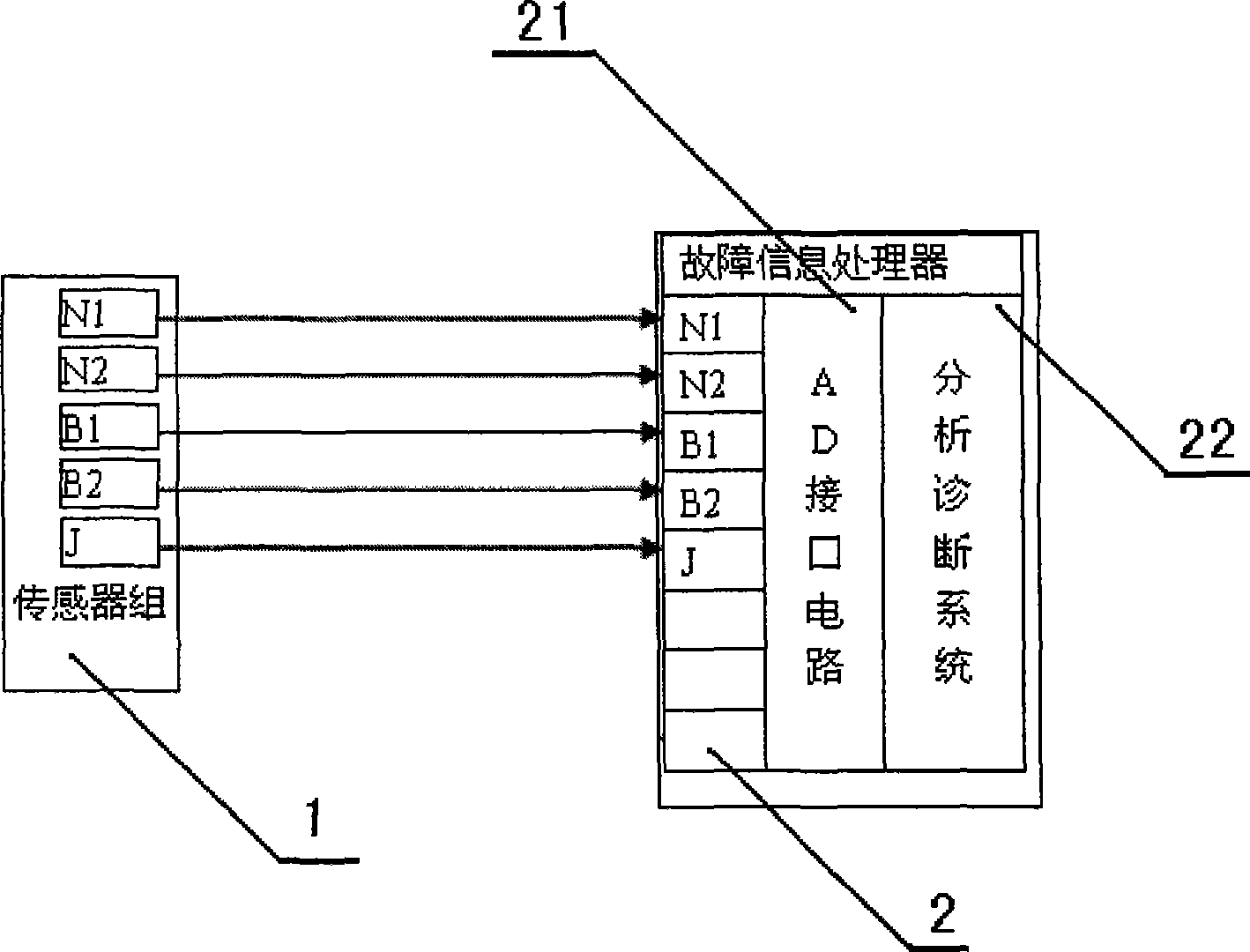
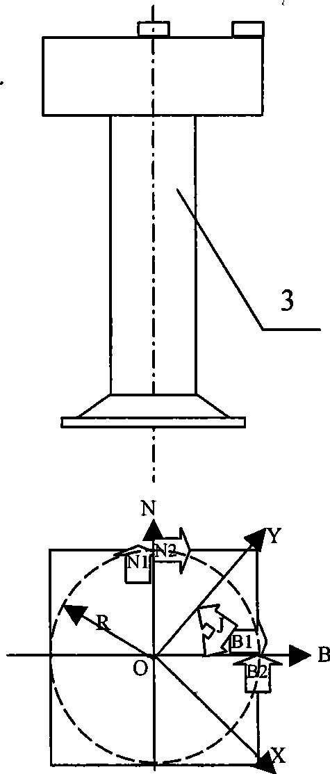
[0053] This mechanical tower fault diagnosis technology includes a sensor group 1 and a fault information processor 2. The sensor group 1 includes sensors N1 installed on the upper layer of the tower and sensitive to the overall north-south direction of the tower according to geographical coordinates (south-east-northwest) and the sensor N1 in the east-west direction. The sensor E1 for vibration, and the sensors N2 and E2 for the torsional vibration of the sensitive tower around its symmetry center 0, also include the polar coordinate sensor J for detecting external effects in the Y direction relative to the east-west direction of the tower and taking the east as a reference; fault information processor 2 Contains AD interface circuit 21 and analysis and diagnosis system (software) 22; sensor output acceleration signals N1, N2, E1, E2, and signal J of force direction angle are respectively connected to the input end of AD interface circuit 21 of fault information processor 2 N1...
Embodiment 2
[0088] Embodiment 2 is a tower center trajectory scheme that simplifies the fault information processor 2 or its AD interface circuit 21 and analysis and diagnosis system 22 into an oscilloscope to directly observe the tower amplitude in real time.
[0089] It is characterized in that the fault information processor is partially replaced by an oscilloscope, and the signal e1 or E1 representing the east-west vibration of the tower output by the separation operator 23 is connected to the X axis of the oscilloscope, and the X axis represents the east; the signal output by the separation operator 23 is The signal n1 or N1 vibrating in the north-south direction of the tower is connected to the Y axis of the oscilloscope, and the Y axis represents the north; when the tower vibrates, the oscilloscope draws the motion amplitude or quasi-acceleration trajectory of the tower center in real time. For example, when a certain speed is displayed in time, the dangerous situation of the tower ...
Embodiment 3
[0090] Embodiment 3, a tower fault diagnosis method, when using the fault information processor to collect N1, N2, E1, E2, J, n1, e1, NZ in real time, use the analysis and diagnosis system (software) 22 to not only draw the tower center trajectory in real time as attached Figure 10-1~10-3 ,(in Figure 10-1 It means that n1=1, b1=B, the amplitude is 0.1m, the frequency is the same, and the phase difference is 90 degrees. At this time, the trajectory of the tower center is a circle with a diameter. Figure 10-2 It shows that the amplitude of n1=N, b1=B is 0.1m, the north-south vibration frequency is 3 times of the east-west vibration frequency, and it is excited by the passing of 3 blades. At this time, the trajectory of the tower center is a 0.2m triple twisted line. Figure 10-3 It means that the amplitude of n=N, b1=B is 0.1m, the north-south amplitude frequency is 3 times of the east-west vibration frequency, and the amplitude is 10 times of the east-west vibration after...
PUM
 Abstract
Description
Claims
Application Information
 - R&D
- Intellectual Property
- Life Sciences
- Materials
- Tech Scout
- Unparalleled Data Quality
- Higher Quality Content
- 60% Fewer Hallucinations
Browse by: Latest US Patents, China's latest patents, Technical Efficacy Thesaurus, Application Domain, Technology Topic, Popular Technical Reports.
© 2025 PatSnap. All rights reserved.Legal|Privacy policy|Modern Slavery Act Transparency Statement|Sitemap|About US| Contact US: help@patsnap.com


