
Fault diagnosis technology for mechanical tower

A fault diagnosis, mechanical tower technology, applied in the testing of machine/structural components, measuring vibration, measuring devices, etc., can solve the problem that it is difficult to propose design requirements and improvement suggestions, there is no safety detection device, and wind turbines are damaged by resonance during operation, etc. question

Active Publication Date: 2013-08-14
北京唐智科技发展有限公司
View PDF3 Cites 0 Cited by
  • Summary
  • Abstract
  • Description
  • Claims
  • Application Information

AI Technical Summary

Problems solved by technology

Even some high-tower equipment with huge influence, such as metallurgical blast furnaces, do not have special safety detection devices
As a result, not only accidents occur from time to time, such as wind turbines being damaged due to operating resonance, and electricity towers and cable towers collapsing due to freezing cables and snowstorms, not to mention the lack of cognitive means for the relationship between these facilities and the environment. Difficult to put forward pertinent design requirements and improvement suggestions

Method used


Image

  • Fault diagnosis technology for mechanical tower
  • Fault diagnosis technology for mechanical tower
  • Fault diagnosis technology for mechanical tower

Examples


Embodiment 1

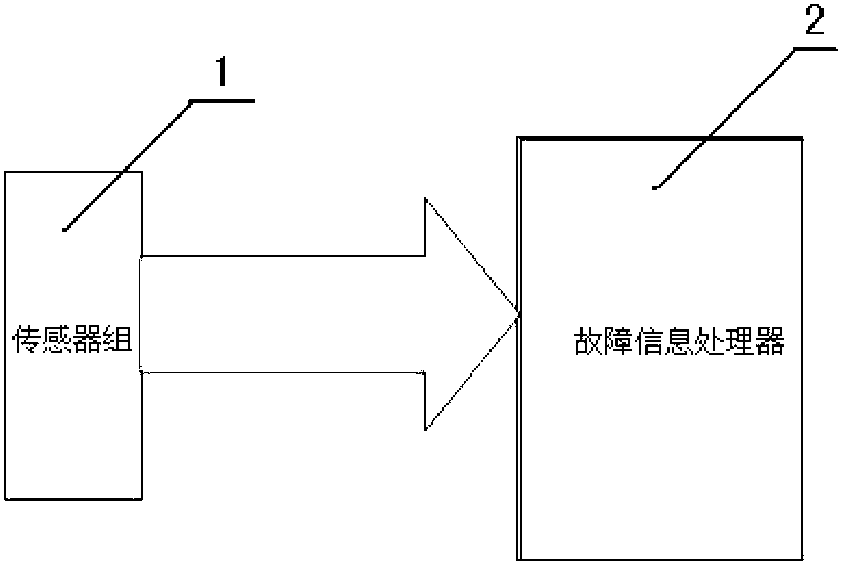
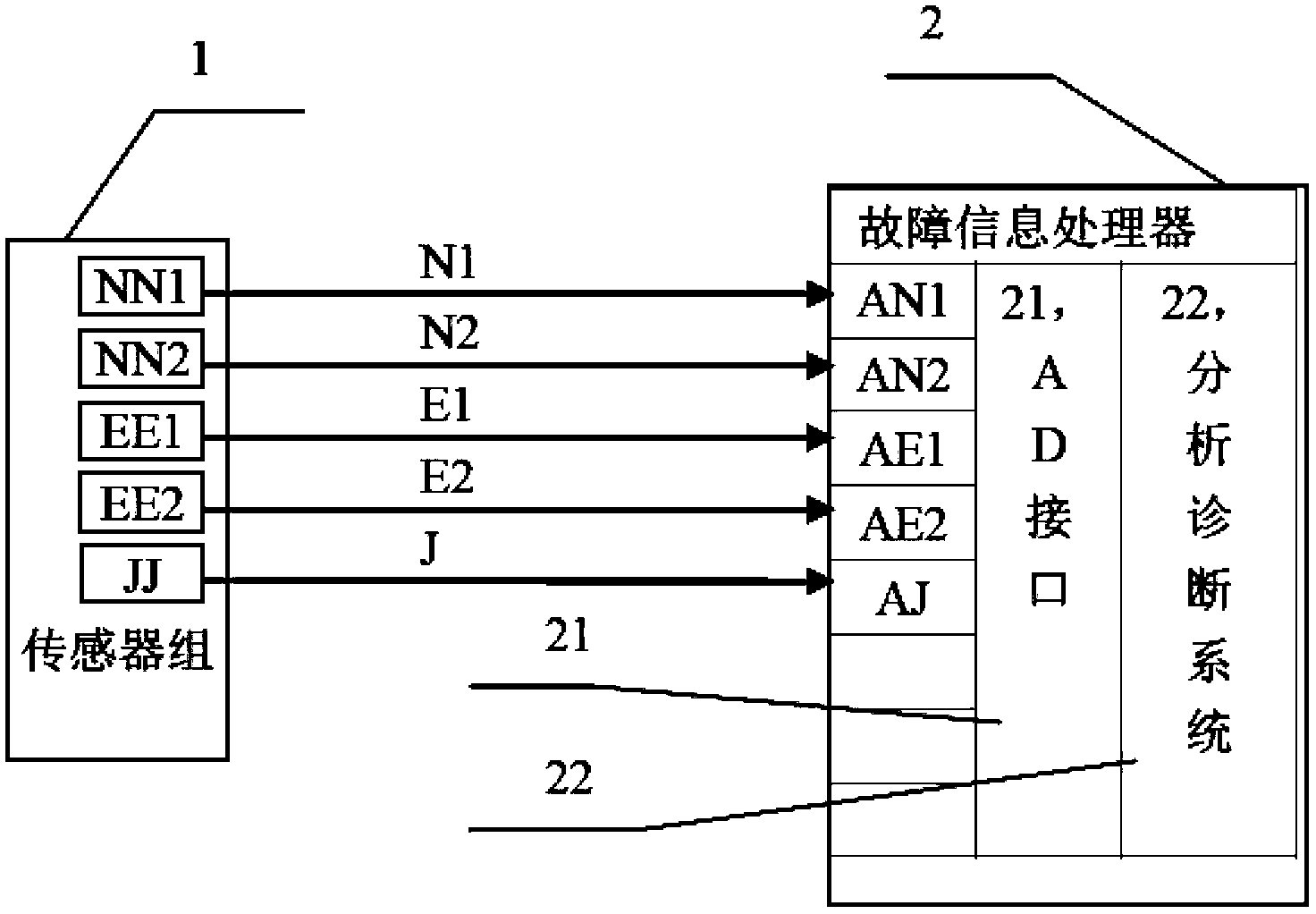
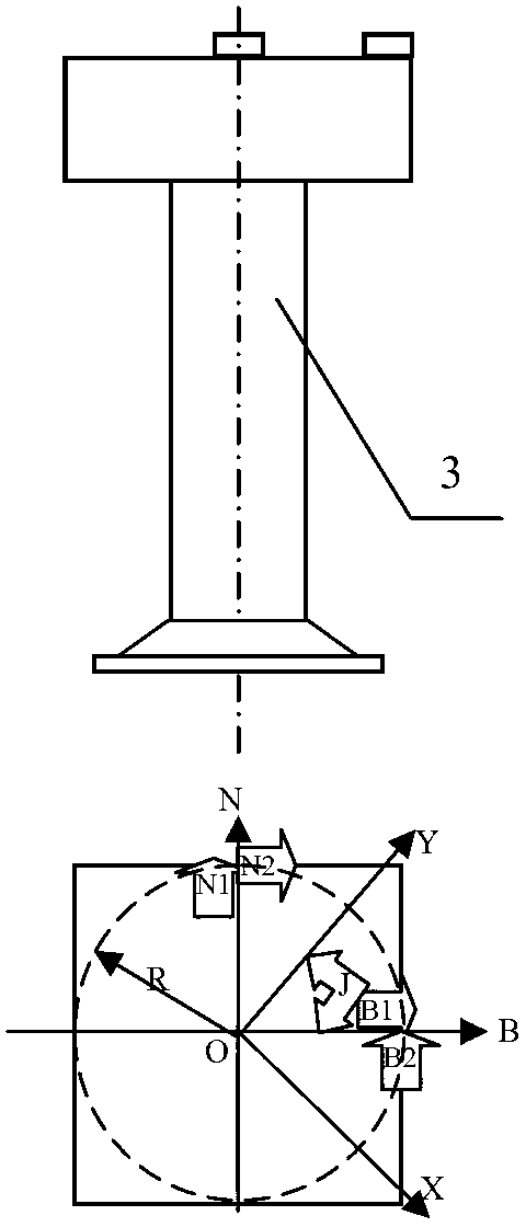
[0063] This mechanical tower fault diagnosis method includes a sensor group 1 and a fault information processor 2. The sensor group 1 includes an acceleration sensor NN1 installed on the upper layer of the tower and sensitive to the overall north-south direction of the tower according to geographic coordinates (east, south, northwest) and east-west Acceleration sensor EE1 for directional vibration, and acceleration sensor NN2, EE2 for torsional vibration of the sensitive tower around its symmetry center O, also includes polar coordinate sensor JJ for detecting the external Y direction relative to the east-west direction of the tower and taking the east as a reference; fault information Processor 2 includes AD interface 21 and analysis and diagnosis system (software) 22; sensor output acceleration signal N1, acceleration signal N2, acceleration signal E1, acceleration signal E2, and the polar coordinate angle J signal of the force direction are respectively connected to the fault...

Embodiment 2

[0105] Embodiment 2 is a tower center trajectory scheme that simplifies the fault information processor 2 or its AD interface 21 and analysis and diagnosis system 22 into an oscilloscope to directly observe the tower amplitude in real time.

[0106] It is characterized in that the fault information processor is partially replaced by an oscilloscope, and the signal lateral vibration e1 or acceleration signal E1 output by the separation operator 23 representing the east-west vibration of the tower is connected to the X axis of the oscilloscope, and the X axis represents the east; 23, the signal lateral vibration n1 or acceleration signal N1 outputted to represent the vibration of the tower in the north-south direction is connected to the Y axis of the oscilloscope, and the Y axis represents the north; when the tower vibrates, the oscilloscope draws the motion amplitude or quasi- acceleration trajectory. For example, it shows in time the dangerous condition of the tower resonance...

Embodiment 3

[0107] Embodiment 3, a tower fault diagnosis method, when the fault information processor is used to collect the acceleration signal N1, acceleration signal N2, acceleration signal E1, acceleration signal E2, polar coordinate angle J, lateral vibration n1, e1, torsional vibration signal in real time NZ, use the analysis and diagnosis system 22 to not only draw the tower center trajectory in real time, as shown in Figures 10-1 to 10-3, (wherein Figure 10-1 shows that the lateral vibration n1 is an N waveform, and the lateral vibration e1 is an E waveform, with an amplitude of 0.1 m and the frequency is the same, and the phase difference is 90 degrees. At this time, the tower center track is a circle with a diameter equal to 0.2m. Figure 10-2 shows that the lateral vibration n1 is an N waveform, and the lateral vibration e1 is an E waveform, with an amplitude of 0.1m. The north-south vibration frequency is three times that of the east-west vibration frequency. When excited by the...


PUM


Abstract

The invention relates to fault diagnosis technology for a mechanical tower, which comprises a sensor group comprising a vibration or / and steady-state acceleration detection sensor and a forced direction detection sensor, and a fault information processor for acquiring signals of the sensor group and analyzing and diagnosing the signals of the sensor group. The signals detected by the sensor groupare transmitted to the fault information processor through cables, the hardware of the fault information processor acquires the signals, and then the corresponding software of the fault information processor performs analytical diagnosis and treatment. Because a plurality of groups of acceleration sensors arranged at a specific position for monitoring the dynamic condition of the tower under a running state are adopted, the technology not only can master the vibration displacement born by the tower along the direction of geographical coordinates, but also can effectively monitor various influences brought by torsional vibration caused by environmental factors and change caused by factors such as individual foundation of a tower body and the like. Simultaneously, aiming at the change factors, the fault information processor matched with the acceleration sensors warns in time within a range of ensuring the normal work of the tower. Therefore, the technology provides a technical support for ensuring the using safety of the tower and improving the service life.

Description

Technical field: [0001] The invention relates to a mechanical tower fault diagnosis method, which belongs to the category of mechanical fault detection and diagnosis technology, and is mainly used for online detection and diagnosis of mechanical towers and cables with vibration detection and analysis technology, such as electric towers and cables of transmission lines, Failures of relay towers for wireless communications, towers for wind power generation, reaction towers for petrochemical equipment, blast furnaces for metallurgical equipment, and high-rise buildings. technical background: [0002] Tower structures are often used in existing buildings, industries, and power facilities. Most towers do not have fault detection devices, but employ what are believed to be sufficiently conservative design codes to ensure safety. Even some high-tower equipment with huge influence, such as metallurgical blast furnaces, does not have special safety detection devices. As a result, n...

Claims


Application Information

Patent Timeline
Patent Type & Authority Patents(China)
IPC IPC(8): G01M7/02G01H1/00G01H1/10
Inventor 唐德尧
Owner 北京唐智科技发展有限公司
Learn More