
Oil varnish mitigation systems

一种油漆、油泵的技术,应用在燃气涡轮发动机领域,能够解决伺服机构损坏、收入损失、故障等问题

Active Publication Date: 2012-04-04
GENERAL ELECTRIC TECH GMBH
View PDF7 Cites 0 Cited by
  • Summary
  • Abstract
  • Description
  • Claims
  • Application Information

AI Technical Summary

Problems solved by technology

Oil-wet components and varnish deposits on other locations can lead to damage and / or failure of these servos and other components
Such damage and failure can result in tripping (or tripping) of the gas turbine engine and subsequent downtime for required repairs resulting in lost revenue

Method used


Image

  • Oil varnish mitigation systems
  • Oil varnish mitigation systems
  • Oil varnish mitigation systems

Examples


Embodiment Construction

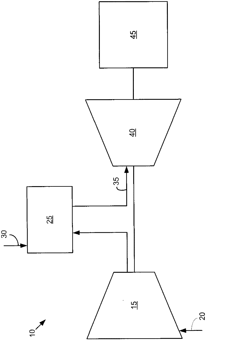
[0054] Referring now to the drawings, wherein like numerals represent like elements throughout the several views, FIG. 1 shows a simplified diagram of a known gas turbine engine 10 . Gas turbine engine 10 may include a compressor 15 . Compressor 15 compresses an incoming air stream 20 . Compressor 15 delivers compressed air stream 20 to combustor 25 . Combustor 25 mixes compressed air stream 20 with compressed fuel stream 30 and ignites the mixture to form combustion air stream 35 . Although only a single combustor 25 is shown, the gas turbine engine 10 may include any number of combustors 25 . Combustion gas flow 35 is then delivered to turbine 40 . Combustion gas flow 35 drives turbine 40 to produce mechanical work. The mechanical work produced in turbine 40 drives compressor 15 and an external load 45, such as a generator or the like.

[0055] Gas turbine engine 10 may use natural gas, various types of syngas, and / or other types of fuels. Gas turbine engine 10 may be ...


PUM


Abstract

The present application provides a lubricating oil varnish mitigation system (200) for a turbine engine (10). The lubricating oil varnish mitigation system (200) may include a lubricating oil circuit (210) with a lubricating oil therein (230) and a hydraulic oil circuit (280) separate from the lubricating oil circuit (210) with a hydraulic oil (300) therein.

Description

technical field [0001] The present application relates generally to gas turbine engines, and more particularly to systems for mitigating lubricating varnish (or varnish, vamish) and possible resultant damage to engine components. Background technique [0002] An important issue in the maintenance and maintenance of known gas turbine engines is the formation of a lubricating varnish film. For example, lubricating oil in a hydraulic circuit may communicate with a number of servo mechanisms that operate inlet guide vanes, gas control valves, liquid fuel valves, and the like. Oil-wet components and varnish deposits on other locations can lead to damage and / or failure of these servos and other components. Such damage and failure can result in tripping (or tripping) of the gas turbine engine, and subsequent downtime for required repairs, resulting in lost revenue. [0003] The formation of paint films can be the result of a complex series of events. Specifically, molecules in a...

Claims


Application Information

Patent Timeline
Patent Type & Authority Applications(China)
IPC IPC(8): F02C7/06F02C7/32
CPCF01D25/20F05B2230/90F01D25/18F05D2230/90F01D25/22F05B2260/95F05D2260/95
Inventor R·J·基拉J·E·梅斯特罗尼E·卡列罗斯P·戈克黑尔
Owner GENERAL ELECTRIC TECH GMBH
Features
  • Generate Ideas
  • Intellectual Property
  • Life Sciences
  • Materials
  • Tech Scout
  • Unparalleled Data Quality
  • Higher Quality Content
  • 60% Fewer Hallucinations
Learn More