
Multi-way reversing valve

A multi-way valve and channel technology, applied in the field of multi-way valves, can solve problems such as pressure rise, random stop devices, flow path switching action obstruction, etc., and achieve the effect of suppressing excessive pressure rise

Active Publication Date: 2012-04-04
FUJIKOKI MFG CO LTD
View PDF9 Cites 9 Cited by
  • Summary
  • Abstract
  • Description
  • Claims
  • Application Information

AI Technical Summary

Problems solved by technology

[0017] In this way, if the outlet side of the high-pressure passage portion 55 is closed during the transition of flow path switching, although the time is very short, there is no place for the high-pressure refrigerant on the discharge side of the compressor to diffuse. As long as the operation of the compressor is not stopped, the high-pressure refrigerant The pressure will rise sharply, which may cause obstacles to the flow channel switching action, and the fault protection mechanism may misjudge that the device is abnormal or malfunction and stop the device indiscriminately.

Method used


Image

  • Multi-way reversing valve
  • Multi-way reversing valve
  • Multi-way reversing valve

Examples


Embodiment Construction

[0034] Next, embodiments of the four-way valve of the present invention will be described with reference to the drawings.

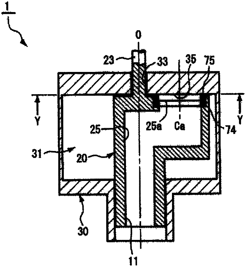
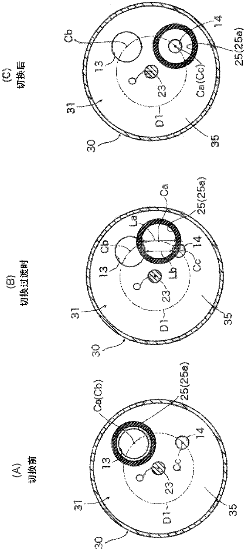
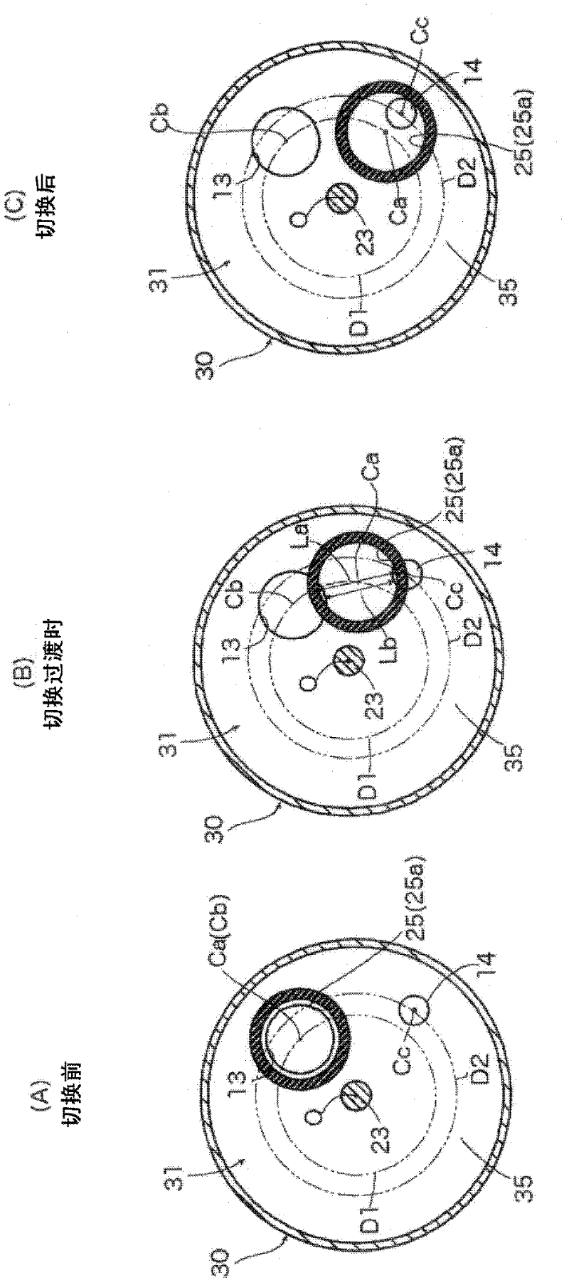
[0035] figure 1 It is a schematic cross-sectional view showing main parts of the first embodiment (the second and third embodiments are basically the same) of the multi-way valve (four-way valve) of the present invention, figure 2 From figure 1 The cross-sectional view viewed in the direction of the Y-Y arrow, image 3 , Figure 4 represent the equivalent of the second and third embodiments respectively figure 2 cross-sectional view. In addition, in the four-way valve 1 of the present embodiment, for the above-mentioned Figure 5 The parts corresponding to the respective parts of the shown conventional four-way valve 1' are denoted by the same symbols, and repeated explanations are omitted.

[0036] The first to third implementations of the present invention are applicable to the above-mentioned Figure 5 In the electric valve, the electric valve...


PUM


Abstract

A multi-way reversing valve is provided to make it possible to prevent the pressure of the high-pressure refrigerant from increasing excessively during the transitional stage of flow path reversal without suspending the operation of the compressor, thereby preventing problems in the flow path reversing operation, while at the same time preventing situations where devices would erratically cause operating as a result of erroneous determinations of an anomaly / failure in the device being made by a fail-safe mechanism. The multi-way reversing valve where a high-pressure passage part into which a high-pressure fluid is introduced is formed in a valve member. A valve seat part and valve chamber are in a valve body. First and second inlet / outlets (selectively in communication with an outlet of the high-pressure passage part) are formed in the valve seat part. A low-pressure fluid is introduced into the valve chamber via the first or second inlet / outlet. An outlet-side end part of the high-pressure passage part is adapted to slide while pressed against a part of the valve seat part between the first and second inlet / outlet during a transitional stage of flow path reversal. The positions / dimensions / shapes of the outlet of the high-pressure passage part (and the first, second inlet / outlets) are designed so the high-pressure passage part outlet is in communication with at least one of the first / second inlet / outlet even during the transitional stage of flow path reversal.

Description

technical field [0001] The present invention relates to a multi-way valve such as a three-way valve and a four-way valve used in heat pumps, etc., and more particularly to a rotary multi-way valve that switches the flow path by rotating the valve core through a driver such as a motor composed of a rotor and a stator. through valve. Background technique [0002] Generally, a heat pump (refrigeration cycle) constituting an air conditioner, a refrigeration device, etc. includes a compressor, a gas-liquid separator, a condenser (outdoor heat exchanger), an evaporator (indoor heat exchanger), and an expansion valve, etc. Four-way valve of the flow path (flow direction) switching unit. [0003] The four-way valve used in such heat pumps basically has a valve element that is rotated by a driver such as a motor, and a valve element that holds the valve element rotatably and is provided with a valve seat portion and a valve chamber, as described in Patent Document 1 below. The valv...

Claims


Application Information

Patent Timeline
Patent Type & Authority Applications(China)
IPC IPC(8): F16K11/06F16K31/04
CPCF16K11/074Y10T137/5544
Inventor 神尾猛
Owner FUJIKOKI MFG CO LTD
Learn More