Thermal energy recovery device and control method

a technology of energy recovery device and control method, which is applied in the direction of pump control, machine/engine, steam engine plant, etc., can solve the problems of insufficient efficiency of reducing pressure in the closed loop, inability to prevent the operation of the safety valve, and inability to force the cooling of the working medium through the use of cooling water

Inactive Publication Date: 2017-10-24
KOBE STEEL LTD
View PDF22 Cites 2 Cited by
  • Summary
  • Abstract
  • Description
  • Claims
  • Application Information

AI Technical Summary

Benefits of technology

[0007]An object of the present invention is to provide a thermal energy recovery device capable of suppressing an excessive rise of pressure in a circulating flow path of the working medium after stopping a circulating pump.
[0020]As described above, according to the present invention, the thermal energy recovery device capable of suppressing an excessive rise of pressure of the working medium in the circulating flow path after stopping the circulating pump can be provided.

Problems solved by technology

However, in the above prior art, a cooling water pump which supplies cooling water to the condenser remains stopped in a state that the power is turned off, so that forced cooling of the working medium by means of the cooling water is not performed.
Therefore, even if the pressure regulating valve opens when the detection value of the pressure sensor exceeds the set value, an efficiency of reducing pressure in the closed loop is not sufficient, and operation of the safety valve cannot always be prevented.

Method used


Image

  • Thermal energy recovery device and control method
  • Thermal energy recovery device and control method
  • Thermal energy recovery device and control method

Examples


first embodiment

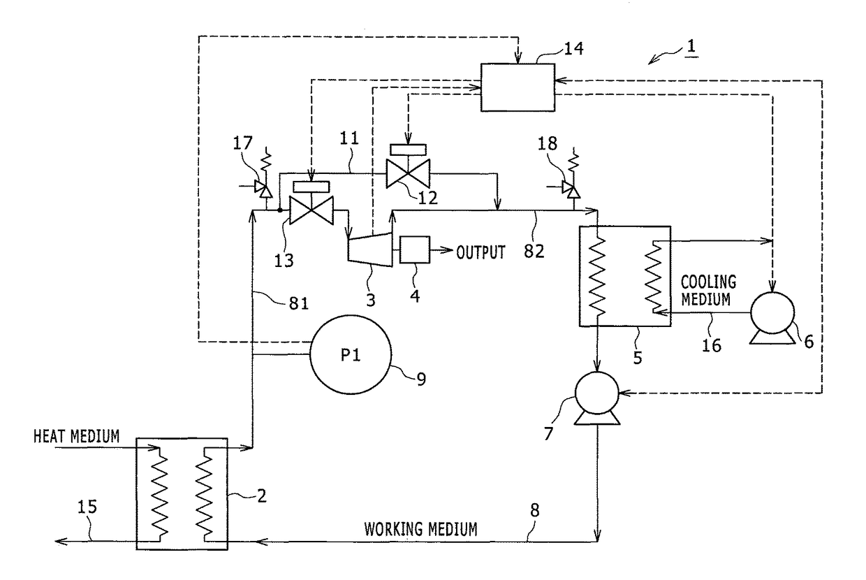
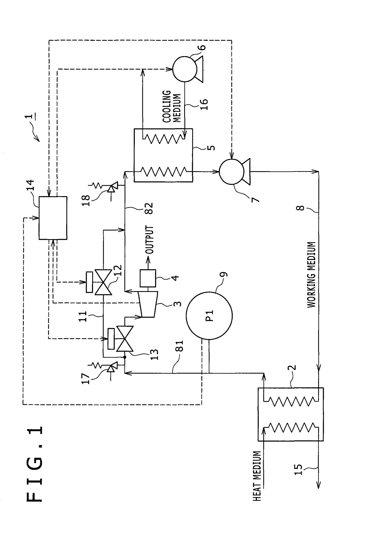
[0026]FIG. 1 is a block diagram showing a configuration of a thermal energy recovery device 1 according to a first embodiment of the present invention. In FIG. 1, solid arrows show flows of various media, and dashed arrows show flows of electric signals. The thermal energy recovery device 1 includes a heater 2, an expander 3, a condenser 5, a circulating pump 7, a generator 4 which is a power recovery machine, a cooling medium pump 6, a circulating flow path 8, and a controller 14. The thermal energy recovery device 1 further includes a shut-off valve 13, an upstream side sensor 9, an upstream side safety valve 17, and a downstream side safety valve 18. The generator 4 is connected to the expander 3. The heater 2, the expander 3, the condenser 5 and the circulating pump 7 are connected to the circulating flow path 8 in this order, and a working medium circulates between these members. For example, as the working medium, low boiling point organic media (Freon or the like) such as R24...

second embodiment

[0045]Next, another operation example of the controller 14 at the time of stoppage of the thermal energy recovery device 1 will be described as a second embodiment. FIG. 4 is a flow chart showing a pressure control operation of the controller 14. The configuration of the thermal energy recovery device 1 is similar to FIG. 1. When the circulating pump 7 is stopped, the pressure P1 of the working medium is detected by the upstream side sensor 9 located in the upstream flow path 81, in a state that the shut-off valve 13 and the bypass valve 12 are closed. Whether the pressure P1 is more than the threshold value th2 or not is determined (step S31). If the pressure P1 is less than the threshold value th2 (the determination is NO), the pressure P1 is detected again after the elapse of a predetermined time. If it is determined that the pressure P1 is more than the threshold value th2 (the determination is YES), the controller 14 performs a communication control for communicating the heater...


PUM


Abstract

A thermal energy recovery device includes: a circulating flow path connected to a heater, an expander, a condenser and a circulating pump for circulating a working medium; a bypass valve in a bypass path connecting the upstream side region and the downstream side region of the expander in the circulating flow path; a power recovery machine connected to the expander; a circulating pump sending the working medium condensed in the condenser to the heater; a cooling medium pump sending a cooling medium to the condenser; an upstream side sensor detecting the pressure / temperature of the working medium on the expander upstream side in the circulating flow path; and a controller controlling the bypass valve and the cooling medium pump. The controller opens the bypass valve after stopping the circulating pump, and drives the cooling medium pump if the pressure / temperature of the working medium on the expander upstream side exceeds a threshold.

Description

BACKGROUND OF THE INVENTION[0001]Field of the Invention[0002]The present invention relates to a thermal energy recovery device for recovering exhaust heat.[0003]Description of the Related Art[0004]Conventionally, thermal energy recovery devices for recovering thermal energy such as geothermal water are known, and a representative thereof is a binary generator.[0005]Japanese Patent Application Laid-Open No. H11-107906 discloses an example of a binary power generation system. The binary power generation system has a closed loop which sequentially connects an evaporator, a screw turbine and a condenser and circulates a working medium. In a bypass path which connects the upstream side and the downstream side of the screw turbine in the closed loop, a pressure regulating valve is provided. The pressure regulating valve opens when a detection value of a pressure sensor provided on the upstream side of the screw turbine in the closed loop exceeds a set value. Between the evaporator and the...

Claims


Application Information

Patent Timeline
Patent Type & Authority Patents(United States)
IPC IPC(8): F01K13/02F01K7/16F03G7/04F01K25/08
CPCF01K7/16F01K13/02F03G7/04F04C2270/80F01K25/08F04C2270/185F01K21/00F01K25/10F01K27/02F02G5/00
Inventor ADACHI, SHIGETOFUKUDA, TAKAYUKIHASHIMOTO, KOICHIRO
Owner KOBE STEEL LTD
Why Eureka
Try Eureka