
Automatic box-type heat treatment equipment

A kind of heat treatment equipment, box-type technology, applied in the direction of lighting and heating equipment, furnace, furnace components, etc., can solve the problems of unbalanced oil temperature in the oil pool, heavy workload, heat energy loss, etc., to improve the quenching method and reduce labor intensity , the effect of prolonging the service life

Inactive Publication Date: 2013-11-20
ANHUI XINNING EQUIP
View PDF6 Cites 0 Cited by
  • Summary
  • Abstract
  • Description
  • Claims
  • Application Information

AI Technical Summary

Problems solved by technology

[0003] The traditional furnace door is difficult to produce, the performance of the selected material is unstable, and the heat deformation is large, resulting in serious heat loss
[0004] In the furnace bottom structure, the furnace bottom plate is directly covered on the resistance wire, the heat conduction speed to the heat-treated workpiece is slow, and the resistance wire is easy to reach or exceed the melting point of the resistance wire in the sealed space, causing the resistance wire to fuse and affecting the heating effect of the furnace.
[0005] In order to prevent the oxide skin from falling into the bottom heating element after the workpiece is heated and cause damage to the heating element, the measures taken in the prior art are: the oxide scale under the furnace bottom plate of the trolley needs to be cleaned regularly, and the furnace bottom plate needs to be lifted when purging , use compressed air to blow off the oxide scales in the resistance wire groove, temporary welding is required during maintenance, the operation is difficult and inconvenient, and the overall workload is large
[0006] The hot oil in the oil pool adopts the traditional wrap-around heat dissipation method, the heat dissipation effect is not ideal, and the oil temperature in the oil pool is not balanced, which directly affects the quality of heat treatment of metal materials

Method used


Image

  • Automatic box-type heat treatment equipment
  • Automatic box-type heat treatment equipment
  • Automatic box-type heat treatment equipment

Examples


Embodiment Construction

[0026] The specific implementation of the present invention will be described in further detail below by describing the embodiments with reference to the accompanying drawings, so as to help those skilled in the art have a more complete, accurate and in-depth understanding of the inventive concepts and technical solutions of the present invention.

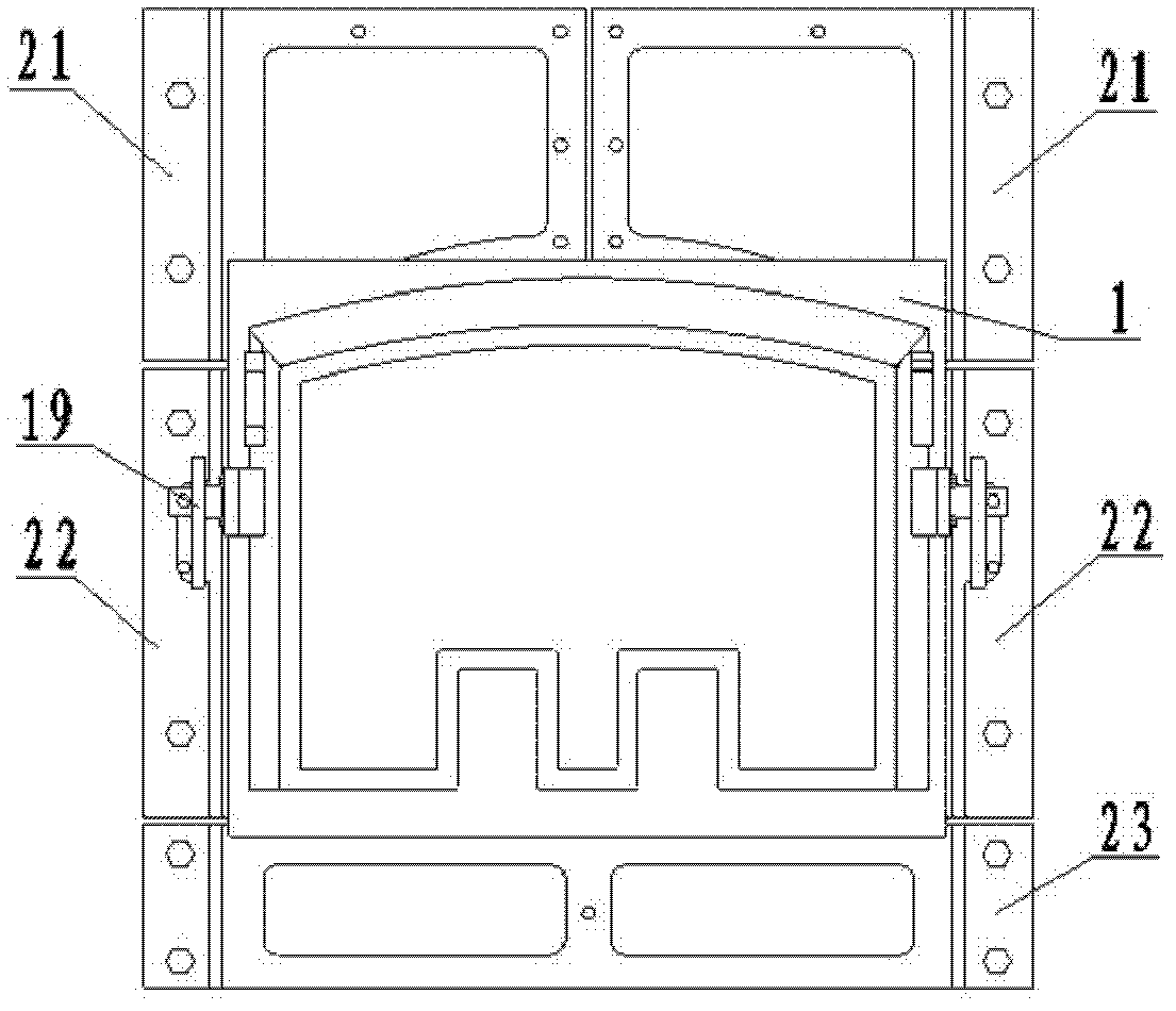
[0027] Such as Figure 1 to Figure 4 The structure of the present invention expressed, the present invention is an automatic box-type heat treatment equipment, including a furnace door 1, a furnace door frame 2, a furnace shell 4, a heating wire 7 and a quenching treatment structure, and the quenching treatment structure includes an oil pool 12.

[0028] The core technology of the invention includes: an improved furnace door structure; a decomposed and combined electric heating wire structure; a silicon carbide cover plate; and a central surge oil cooling circulation system. The analysis and introduction are as follows:

[0029] ...


PUM


Abstract

The invention discloses automatic box-type heat treatment equipment, which comprises a furnace door (1), a furnace door framework (2), a furnace shell (4), a heating wire (7) and a quenching treatment structure, wherein the quenching treatment structure comprises an oil pool (12); the furnace door framework (2) is made of a cast iron material; the furnace door (1) is provided with a furnace door brick (3) made of a refractory material; and the furnace door brick (3) and the furnace door (1) are connected into a whole. By the technical scheme, the thermal efficiency of the equipment is improved, energy is saved, the operation is simple and convenient, and the labor intensity is reduced; the equipment is protected and the service life of the equipment is prolonged; and a quenching mode is improved, the temperature of quenching oil is further reduced and is kept equal, and the quenching quality of products is effectively ensured.

Description

technical field [0001] The invention belongs to the technical field of industrial heat treatment equipment, and relates to the technology of heat treatment of metal materials. More specifically, the invention relates to an automatic box-type heat treatment equipment. Background technique [0002] With the large-scale development of heat treatment technology, the modernization requirements for metal material heat treatment equipment are getting higher and higher. Traditional heat treatment equipment has high energy consumption, difficult equipment maintenance, and high maintenance costs, which largely restrict production. Specifically, there are the following issues: [0003] The traditional furnace door is difficult to manufacture, the properties of the selected materials are unstable, and the heat deformation is large, resulting in serious heat loss. [0004] In the furnace bottom structure, the furnace bottom plate is directly covered on the resistance wire, the heat cond...

Claims


Application Information

Patent Timeline
Patent Type & Authority Patents(China)
IPC IPC(8): F27B3/00F27B3/10F27D1/18C21D1/18C21D1/40
Inventor 罗明松王登国
Owner ANHUI XINNING EQUIP
Learn More