Lubricating device for engine

a technology for lubricating devices and engines, applied in the direction of auxilary lubrication, lubrication elements, pressure lubrication, etc., can solve the problems of concentrating machining on the crank case and reducing the efficiency of machining, so as to reduce the man-hour of machining and prevent the increase of oil temperature

Inactive Publication Date: 2007-04-12
HONDA MOTOR CO LTD
View PDF7 Cites 8 Cited by
  • Summary
  • Abstract
  • Description
  • Claims
  • Application Information

AI Technical Summary

Benefits of technology

[0011] Still further, the structure is such that the oil pump and the crank case are arranged separately from each other, thereby making it difficult for the effect of the heat from the crank case to be exerted on the oil pump, and t

Problems solved by technology

H11-311126, described above, one of the pair of case half bodies forming the crank case needs to be subjected to machining for formi

Method used


Image

  • Lubricating device for engine
  • Lubricating device for engine
  • Lubricating device for engine

Examples


Embodiment Construction

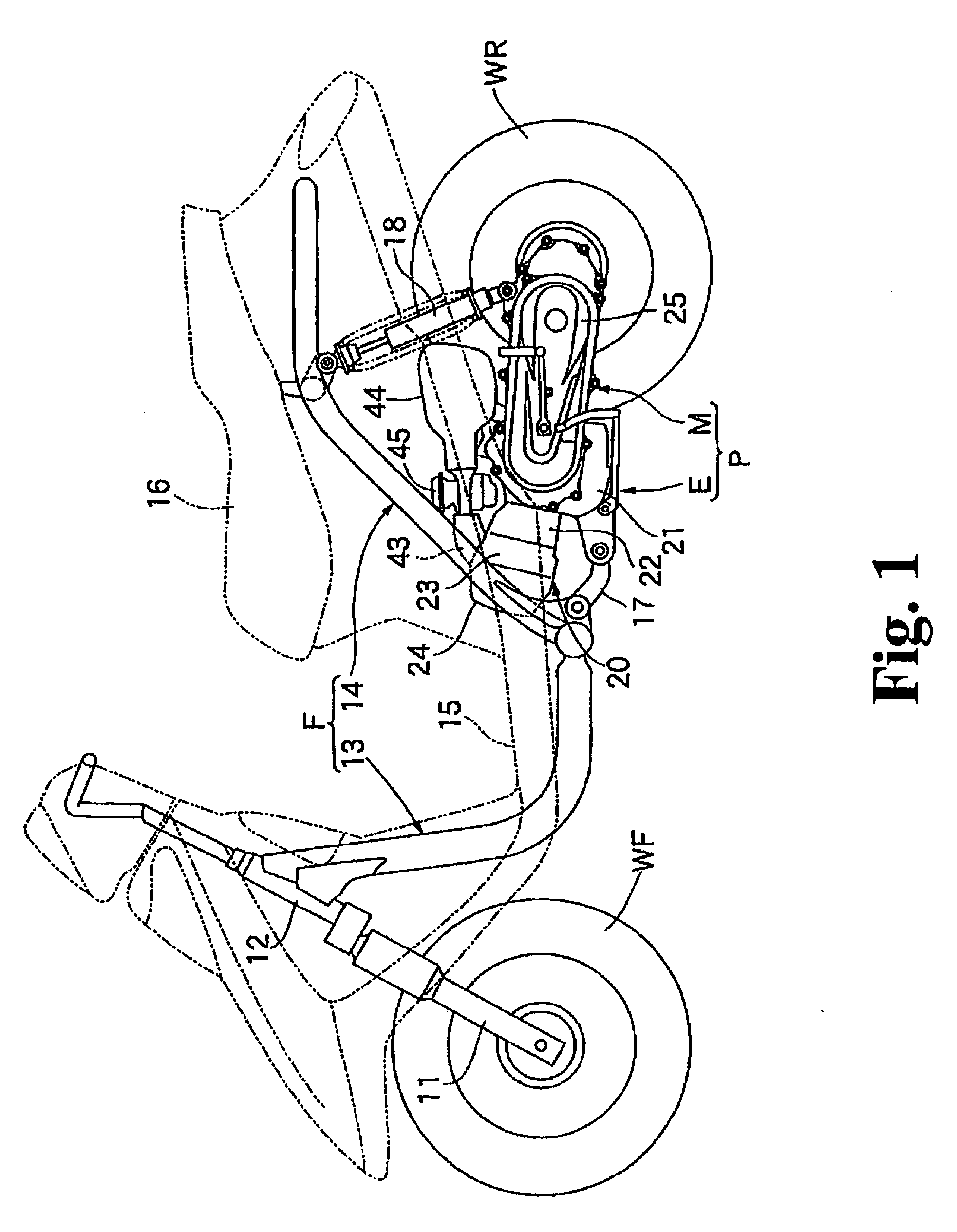
[0019] First, in FIG. 1, a vehicle body frame F of the scooter-type motorcycle includes: a front frame 13 which extends downward toward the rear from a head pipe 12 steerably supporting a front fork 11 pivotably supporting a front wheel WF and which supports a step floor 15; and a rear frame 14 which extends upward toward the rear from the rear part of the front frame 13 and which supports an occupant seat 16. In the vehicle body frame F, a power unit P which includes an engine E and a belt-type continuously variable transmission M, which continuously varies the power of engine E transmitted to a rear wheel WR. Power unit P is suspended via a suspension link 17 in such a manner as to be vertically swingable. Between the rear frame 14 and the power unit P, a rear damper 18 is provided for damping the vertical swinging of the power unit P.

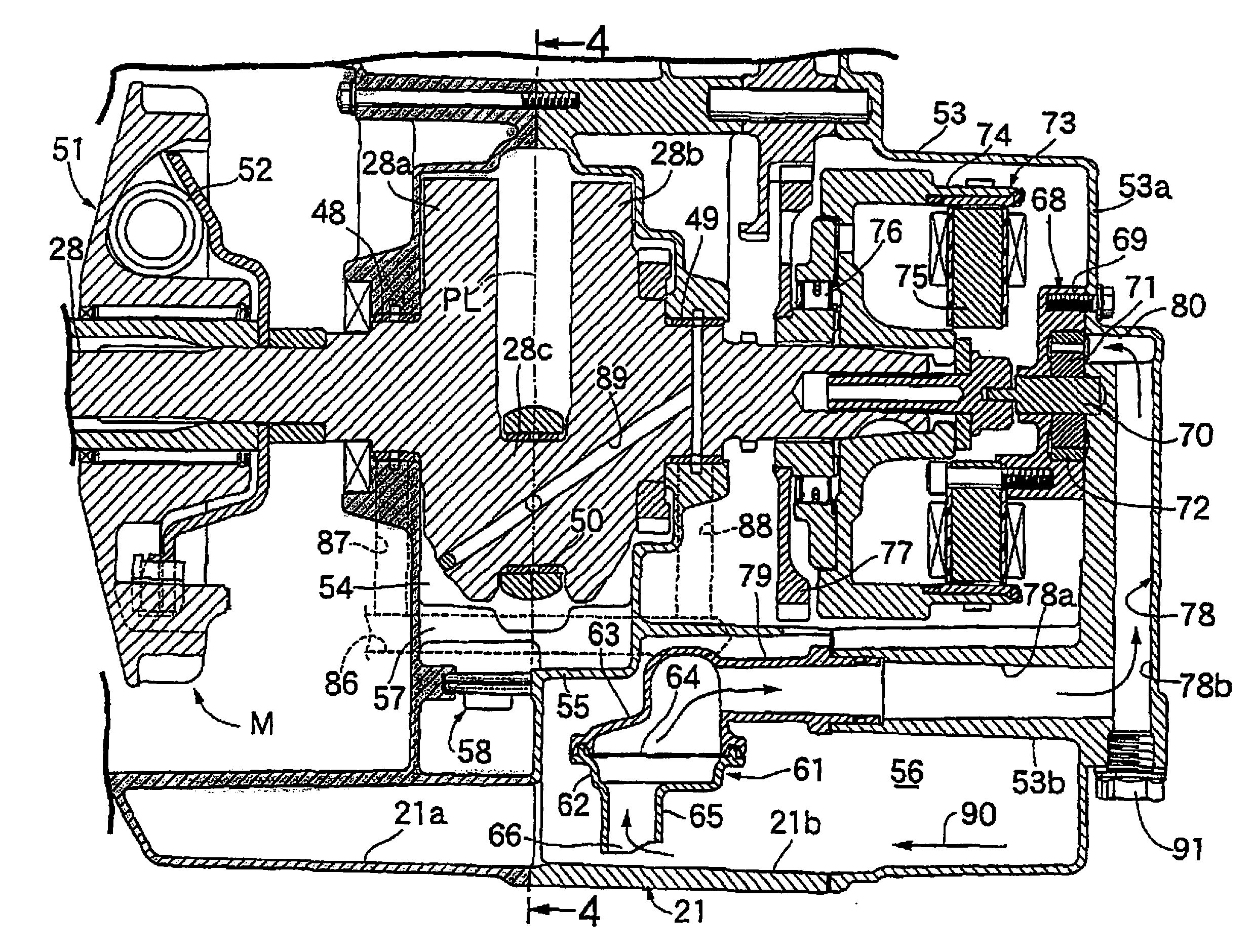
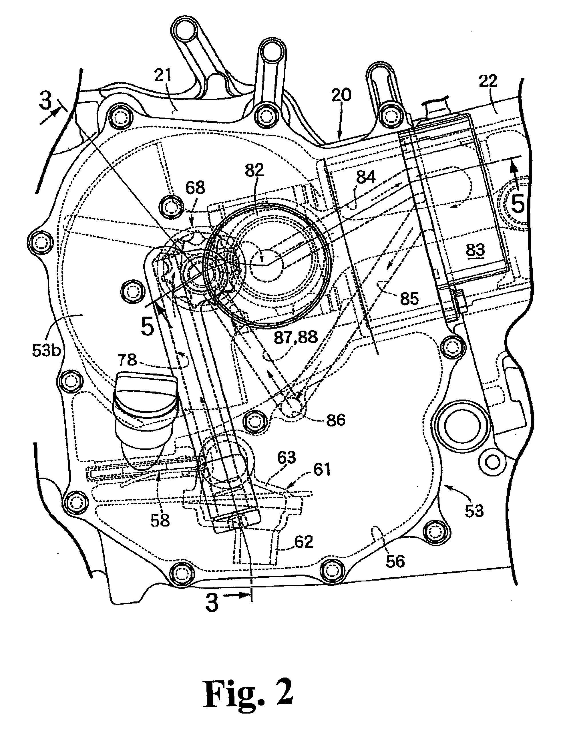
[0020] Referring to FIGS. 2 to 4 together, an engine body 20 of the engine E is provided with: a crank case 21; a cylinder block 22 which is couple...


PUM


Abstract

An lubrication device for an engine includes: a crank case which freely rotatably supports a crank shaft and also which stores oil at its lower part; an oil strainer which is so arranged as to be fixed in the crank case; and an oil pump which suctions the oil at the lower part in the crank case via the oil strainer. In the lubricating device, the machining efficiency can be improved by reducing the time of machining to a crank case to thereby decentralize machining processes, and also the oil temperature can be reduced. A crank case cover covering part of a crank case and coupled with the crank case is provided with an oil suction passage which leads to an oil pump, and an oil strainer communicates with the oil suction passage via a connecting pipe which is a member different from the crank case

Description

BACKGROUND OF THE INVENTION [0001] The present invention relates to a lubricating device for an engine provided with a crank case which freely rotatably supports a crank shaft and also which stores oil at its lower part, an oil strainer which is so arranged as to be fixed in the crank case, and an oil pump which sucks the oil at the lower part in the crank case via the oil strainer. [0002] Already known, for example, by Japanese Patent document JP-A No. H11-311126 is an oiling device which has, in a crank case made up a pair of case half bodies mutually coupled together on a plane including a cylinder axis, an oil strainer so arranged as to be supported by one of the case half bodies, an oil pump fitted to the other one of the case half bodies, and an oil suction passage linking between the oil strainer and the oil pump. SUMMARY OF THE INVENTION [0003] However, with the oiling device disclosed in JP-A No. H11-311126, described above, one of the pair of case half bodies forming the c...

Claims


Application Information

Patent Timeline
IPC IPC(8): F01M1/06
CPCF01M1/02F01M11/0004F01M11/02F01M2001/0269F01M2001/0284F01M2011/0066
Inventor OKI, KENJI
Owner HONDA MOTOR CO LTD
Why Eureka
Try Eureka