Supercharge Your Innovation With Domain-Expert AI Agents!

Optical touch system

An optical touch and touch point technology, applied in the fields of instruments, electrical digital data processing, data processing input/output process, etc., can solve the problem of not fully satisfying the multi-touch technology and so on.

Inactive Publication Date: 2012-04-04
QUANTA COMPUTER INC
View PDF3 Cites 1 Cited by
  • Summary
  • Abstract
  • Description
  • Claims
  • Application Information

AI Technical Summary

Problems solved by technology

However, the traditional positioning method of simply measuring the angle to determine the coordinates of the touch point based on the image received by the sensor cannot fully meet the needs of multi-touch technology.

Method used


Image

  • Optical touch system
  • Optical touch system
  • Optical touch system

Examples


Embodiment Construction

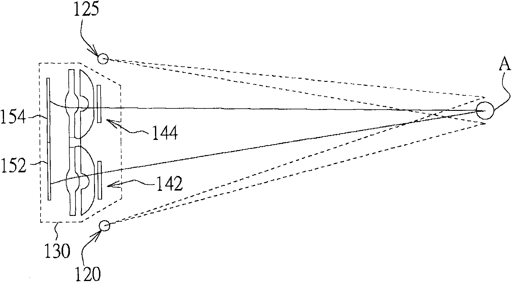
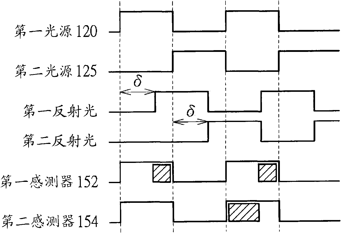
[0022] The present invention provides an optical touch control system. By calculating the phase difference between different reflected lights to obtain the distance information between the touch point and the sensing module, and combining the angle information of the touch point, it is possible to improve the judgment of the coordinates of the touch point. the accuracy.

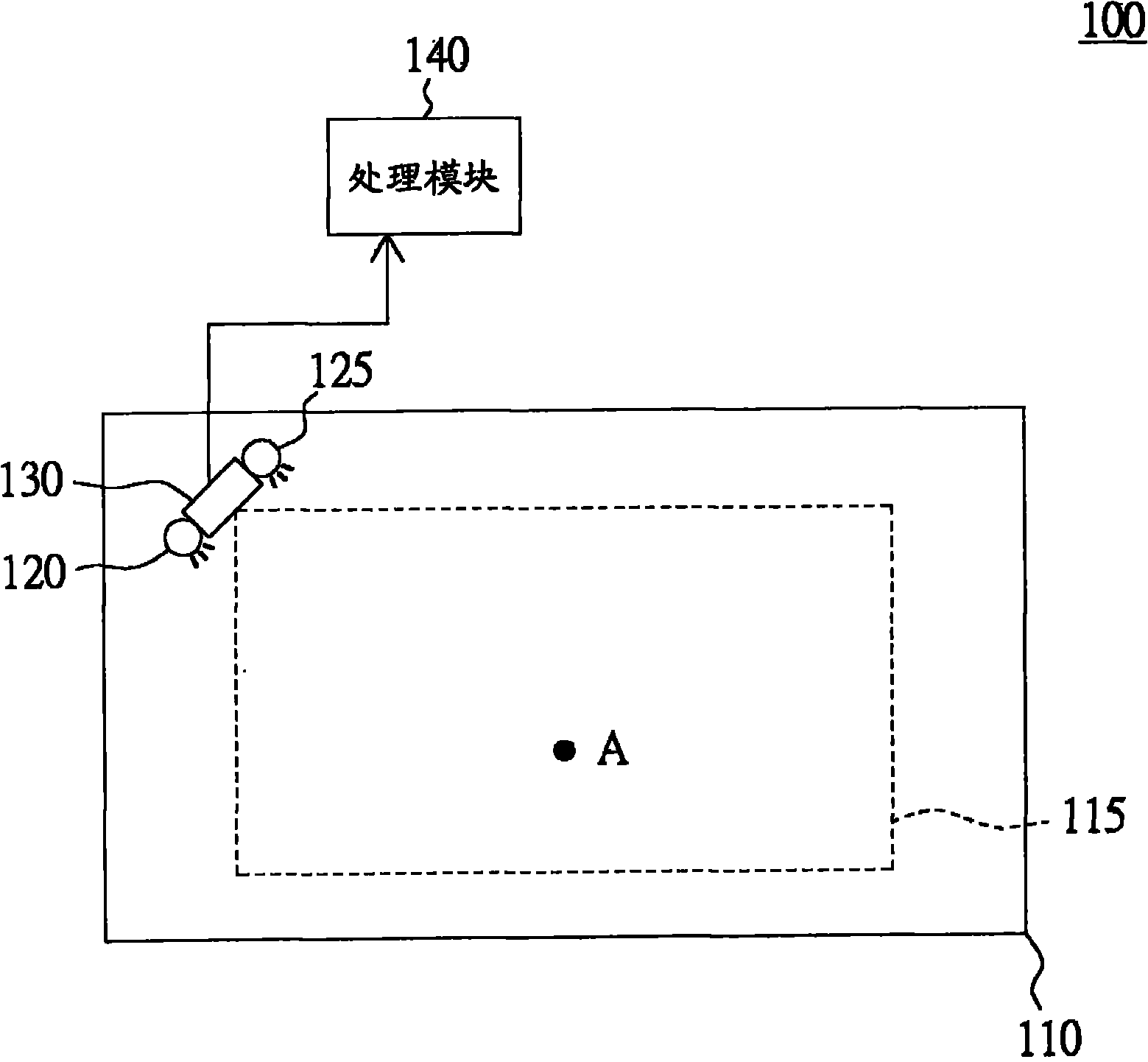
[0023] Please refer to figure 1 , which is a schematic diagram of an optical touch system according to a preferred embodiment of the present invention. The optical touch system 100 is used for determining the coordinates of touch points on a panel 110 . On the panel 110 , a touch area 115 can be defined by various optical elements such as light guide strips or mirrors. The optical touch system 100 includes a first light source 120 , a second light source 125 , a sensing module 130 and a processing module 140 . The lighting frequencies of the first light source 120 and the second light source 125 are the sa...


PUM


Abstract

The invention discloses an optical touch system, which comprises a first light source, a second light source, a sensing module and a processing module. A lightening time sequence of the second light source is one phase different from a lightening time sequence of the first light source. The sensing module is used for acquiring a sensing image of a touch point of a panel and receiving first reflected light of the touch point corresponding to the first light source and second reflected light of the touch point corresponding to the second light source; and the processing module is used for acquiring angle information according to the sensing image, calculating phase difference between the first reflected light and the second reflected light to acquire distance information, and determining a coordinate corresponding to the touch point according to the angle information and the distance information.

Description

technical field [0001] The invention relates to an optical touch system, and in particular to a high-precision optical touch system. Background technique [0002] Due to the convenient and intuitive operation of the touch screen, the touch screen is widely used in various electronic products, such as handheld electronic devices, desktop computers or cash machines. Currently, touch screens can be classified into resistive, capacitive, ultrasonic and optical touch screens according to sensing principles. For the optical touch screen, when the user's finger or a stylus or other object is located in the touch area, part of the light emitted by the light source is blocked by the object. In this way, according to the image received by the sensor, the coordinates of the touch point of the object in the touch area can be determined. [0003] However, with the advancement of technology, the demand for multi-touch technology is becoming more and more extensive. However, the traditi...

Claims


Application Information

Patent Timeline
Patent Type & Authority Applications(China)
IPC IPC(8): G06F3/042
Inventor 林秉忠林振宽陈育琛林宜蒨
Owner QUANTA COMPUTER INC
Features
  • R&D
  • Intellectual Property
  • Life Sciences
  • Materials
  • Tech Scout
  • Unparalleled Data Quality
  • Higher Quality Content
  • 60% Fewer Hallucinations
Learn More