
Belt monitoring system for carrying device

A technology for monitoring systems and handling equipment, which is applied in transportation and packaging, conveyor control devices, conveyor objects, etc., and can solve the problems of suspended equipment with or without load that cannot be prevented in advance, maintenance increases, and early warning cannot be achieved.

Inactive Publication Date: 2012-04-11
AU OPTRONICS CORP
View PDF6 Cites 2 Cited by
  • Summary
  • Abstract
  • Description
  • Claims
  • Application Information

AI Technical Summary

Problems solved by technology

[0006] In the existing method, the biggest problem faced by the proximity switch is that the problem can only be found after the belt breaks, and the effect of early warning cannot be achieved.
And at this time, the position of the suspended equipment and whether there is a load cannot be prevented in advance. Once a situation occurs, the follow-up treatment and maintenance will increase its difficulty

Method used


Image

  • Belt monitoring system for carrying device
  • Belt monitoring system for carrying device
  • Belt monitoring system for carrying device

Examples


Embodiment Construction

[0032] In order to make the description of the present invention more detailed and complete, reference may be made to the attached drawings and various embodiments described below, and the same numbers in the drawings represent the same or similar elements. However, the provided embodiments are not intended to limit the scope of the present invention, and the description of the structure and operation is not intended to limit the order of its execution. Any device recombined by components to produce devices with equivalent functions is the subject of this invention. scope covered by the invention. The drawings are for illustration purposes only and are not drawn to original scale. On the other hand, well-known elements and steps have not been described in the embodiments in order to avoid unnecessarily limiting the invention.

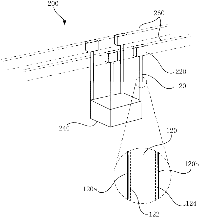
[0033] see figure 1 and figure 2 , figure 1 A schematic diagram of a transporting device 200 according to an embodiment of the present invention i...


PUM


Abstract

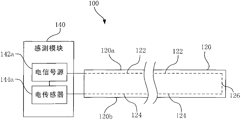
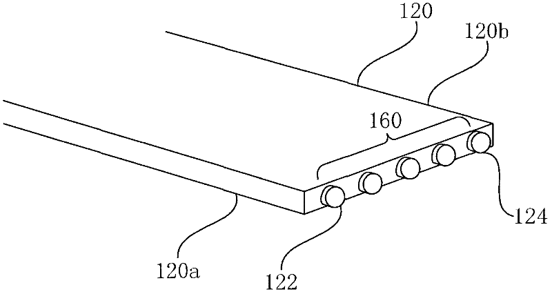
The invention provides a belt monitoring system for a carrying device, the belt monitoring system comprises a belt and a sensing module. Wherein, a belt comprises a first signal line, a second signal line, and a connecting circuit. The first signal line is embedded at one side edge adjacent to the belt, the second signal line is embedded at the other side edge adjacent to the belt. The connecting circuit is disposed at one end of the belt, and connected between the first signal line and the second signal line, the first signal line, the connecting circuit, and the second signal line form a loop. The sensing module is disposed at the other end of belt and is respectively connected to the first signal line and the second signal line, the sensing module is used to sense whether the loop is off. The belt monitoring system in the invention is advantageous in that, sensing is performed via various singlas, and real-time monitoring of whether crack happens at the two side edges of the belt is performed, therefore, discovery in advance of complete crack of the belt is made, and necessary repair is performed.

Description

technical field [0001] The present invention relates to a monitoring system, and in particular to a detection system for monitoring belt breakage. Background technique [0002] In modern industrial society, automatic control system gradually replaces manpower and becomes the key to improve production efficiency. In particular, the advanced semiconductor manufacturing process has introduced a large number of automated equipment to perform various precision manufacturing steps to reduce costs and human errors. [0003] For example, in a semiconductor factory, it is common to see a grinder table for grinding wafers, a robotic arm for grabbing wafers, and conveying equipment for transferring wafers or glass substrates, etc. Among the above-mentioned equipment, belt structures are often seen as power transmission or suspension of heavy objects. [0004] Taking the existing suspended conveying equipment as an example, it usually includes a lifting belt connected with a driving m...

Claims


Application Information

Patent Timeline
Patent Type & Authority Applications(China)
IPC IPC(8): B65G43/02
Inventor 郑允睿王绍义
Owner AU OPTRONICS CORP
Learn More