Eye protection equipment and method of high power light signal transmission system

A transmission system, optical signal technology, applied in transmission systems, electromagnetic wave transmission systems, electrical components, etc., to achieve the effect of no communication response protocol, reliable protection function, and simple equipment structure

Inactive Publication Date: 2007-02-14
FENGHUO COMM SCI & TECH CO LTD
View PDF0 Cites 2 Cited by
  • Summary
  • Abstract
  • Description
  • Claims
  • Application Information

AI Technical Summary

Problems solved by technology

[0005] The technical problem to be solved by the present invention is to provide an eye protection device and method for a high-power optical signal transmission system, simplify the structure of the device, and especially solve the judgment of reliable recovery of the line when there is no auxiliary optical channel and transmission message protocol And carry out problems such as automatic exit of eye protection to restore the normal business transmission of the system

Method used


Image

  • Eye protection equipment and method of high power light signal transmission system
  • Eye protection equipment and method of high power light signal transmission system
  • Eye protection equipment and method of high power light signal transmission system

Examples


Embodiment 1

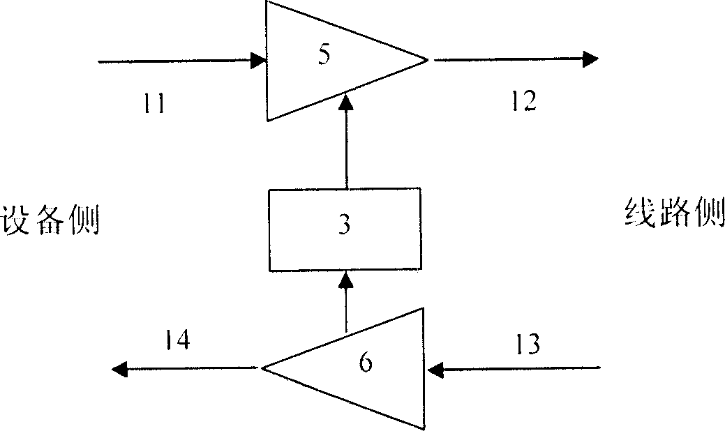
[0070] Example as image 3 As shown, the optical signal 11 output by the equipment transmitter is sent to the optical power amplifier 5 to be amplified and then becomes a line output optical signal 12, which is sent to the optical fiber transmission line; the opposite line input optical signal 13 transmitted by the optical fiber line is passed through the optical preamplifier 6 After being amplified, the device receives the optical signal 14 and sends it to the device receiver; the state of the line input optical signal 13 monitored by the optical preamplifier 6 is sent to the machine disk controller 3, and then the optical power amplifier 5 is controlled after analysis and processing. working status.

Embodiment 2

[0071] Example two such as Figure 4 As shown, the optical signal 11 output by the equipment transmitter is sent to the optical power amplifier 5 to amplify and become a line output optical signal 12 and then sent to the optical fiber transmission line; the opposite line input optical signal 13 transmitted by the optical fiber line is divided by the optical coupler 7 A part of the light is sent to the optical power detector 8 to monitor the input optical signal, while the main optical signal is sent to the equipment receiver as the equipment receiving optical signal 14; the state of the line input optical signal monitored by the optical power detector 8 is sent to The disk controller 3 controls the working state of the optical power amplifier 5 after analysis and processing.

Embodiment 3

[0072] Embodiment three such as Figure 5 As shown, the optical signal 11 output by the transmitter of the device is sent to the optical power amplifier 5 to be amplified to become a line output optical signal 12 and then sent to the optical fiber transmission line; the input optical signal 13 of the opposite end line transmitted by the optical fiber line is directly sent to the optical receiver of the device The machine 9 performs optical signal reception; the equipment optical receiver 9 sends the monitored state of the line input optical signal to the machine disk controller 3 while receiving the optical signal, and then controls the working state of the optical power amplifier 5 after analysis and processing.


PUM


Abstract

This invention relates to an eye protection device and a method for a large power signal transmission system, in which, an optical power detector PD sends the monitored signal state of input light to a BCT to control an optical control unit OCU to regulate the output optical signals to a related data state and communicate with a host device management computer, which does not use any additional optical wave channels to monitor the broken and resuming of optical transmission lines and enter into and retreat from the eye protection state.

Description

technical field [0001] The invention relates to the technical field of long-distance optical communication, in particular to SDH, IP and WDM optical transmission systems that require high-power optical output. Background technique [0002] With the extension of optical communication transmission distance, it is more and more common to use high-power optical transmission devices and optical power amplifiers in optical communication systems, and the signal optical power also tends to increase rapidly. However, in normal times, this kind of high-power optical signal that can be well restrained in the core layer of the communication fiber will leak into the free space once the fiber breaks, which may cause serious damage to the personnel who come into contact with the fiber section. , especially the eye damage caused by the repair personnel of optical fiber lines. Due to the potential safety hazards of high-power optical signals, the IEC has clear regulations on the upper limit...

Claims


Application Information

Patent Timeline
Patent Type & Authority Applications(China)
IPC IPC(8): H04B10/17H04B10/03
Inventor 雷非陈德华谭本明王红启
Owner FENGHUO COMM SCI & TECH CO LTD
Why Eureka
Try Eureka