Positive feeder unit for feeding wire at constant tension

A metal wire, tension sensor technology, used in the transportation of filamentous materials, transportation and packaging, inductance/transformer/magnet manufacturing, etc., can solve problems such as no description

Active Publication Date: 2016-03-16
B T S R INT
View PDF8 Cites 0 Cited by
  • Summary
  • Abstract
  • Description
  • Claims
  • Application Information

AI Technical Summary

Problems solved by technology

However, the known solutions do not describe a feeder device for feeding the wire in which this feeding can be achieved by measuring a parameter of the wire during the feeding of the wire (wire feeding amount and wire feed speed) in a fully automatic manner under controlled constant tension
In other words, the feeding of the wire in said prior patent is not carried out by means of the operation of the automatic feeder, through the measurements made by the feeder of the aforementioned parameters of the wire

Method used


Image

  • Positive feeder unit for feeding wire at constant tension
  • Positive feeder unit for feeding wire at constant tension
  • Positive feeder unit for feeding wire at constant tension

Examples


Embodiment Construction

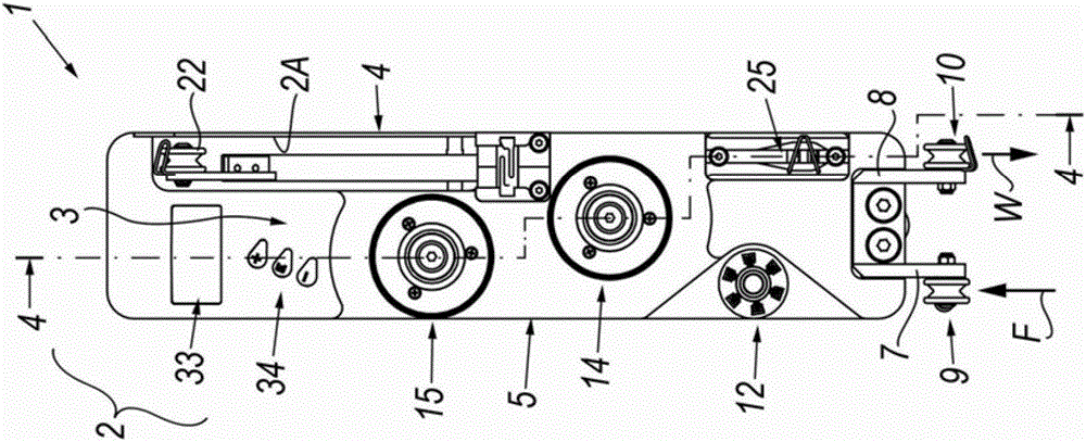
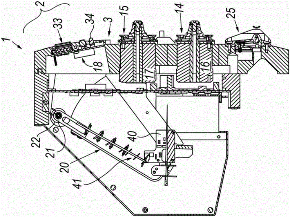
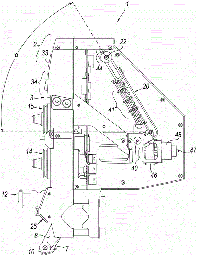
[0036]Referring to said figures, the wire feeder device is generally indicated at 1 and comprises a main body or housing 2 comprising a front 3 and sides 4 and 5 . The sides 4 and 5 are closed by cover elements which are not in the figure 2 with 3 shown in .

[0037] There are parallel supports 7 and 8 on, or associated with and protruding from, the front face 3 (cf. figure 1 Starting from the bottom of the main body 2 ), the supports 7 and 8 support corresponding grooved rollers 9 or 10 which rotate freely on pins fixed to the respective supports. The purpose of the rollers 9, 10, preferably made of ceramics, is to define the trajectories of the wire from the spool (not shown) to the device 1 and from the device 1 to the processing machine (also not shown), these trajectories are indicated by F and W respectively . The fact that the rollers are made of ceramic (or an equivalent low coefficient of friction material) minimizes the friction between the wire and the roller, ...


PUM


Abstract

A metal wire feeder device including a body presenting a wire braking member, one or more pulleys driven by respective motors about which the wire is wound, the wire before reaching a processing machine passing through a compensator member and a tension sensor, an electronic control unit able to continuously measure the tension value and make it uniform at a predetermined value by acting on a first regulator loop operating on the motors and a second regulator loop operating on the compensator member. The electronic control unit operates automatically in making the tension uniform at the predetermined value, on the basis of the fed wire quantity or of the wire feed velocity.

Description

technical field [0001] The invention relates to a wire feeder device according to the introduction of the independent claims. Background technique [0002] A number of industrial production methods (electric motor manufacturing, coil construction, etc.) are known in which the wires to be wound on physical supports, which may assume different shapes, are formed of different materials and formed into finished products or only during the production phase (as in the case of what is known as "coiling in air" by means of temperature-dependent self-adhesive wires). [0003] In these processes, tension control is the basis for ensuring continuity and quality of the finished product. For example, proper tension control ensures the formation of high-quality square coils by allowing the wire to adhere precisely to the support—even near the corners of the support—and thus avoids the known colloquial "soft coil" problem. Condition. [0004] The tension applied to the coil can also e.g...

Claims


Application Information

Patent Timeline
Patent Type & Authority Patents(China)
IPC IPC(8): B65H59/38H01F41/096H01F41/094
CPCB65H59/388B65H2701/36H01F41/094B65H59/38B21C47/003B21C47/345B65H59/18
Inventor 蒂齐亚诺·巴雷亚
Owner B T S R INT
Why Eureka
Try Eureka