Apparatus for dyeing textile substrates with foamed dye

a textile substrate and foaming technology, applied in textiles, other washing machines, liquid/gas/vapor textile treatment, etc., can solve the problems of inability to dye cellulosic textile materials with indigo dye, waste dye and water disposal, undesirable substantial expense and environmental problems, etc., to achieve the effect of reducing the entry ra

Active Publication Date: 2011-03-29
GASTON SYST INC
View PDF42 Cites 18 Cited by
  • Summary
  • Abstract
  • Description
  • Claims
  • Application Information

AI Technical Summary

Benefits of technology

[0010]In this preferred embodiment, the inert gas is nitrogen and the foam generator generates a foam of nitrogen containing the leuco-state dye. One advantage of nitrogen being in the foam is that when the foam collapses in the chamber, the nitrogen increases the amount of inert nitrogen in the chamber environment.
[0013]In another form of the present invention, the apparatus is directed to dyeing a traveling textile fabric substrate in a housing having an interior chamber through which the substrate travels. An entry roller assembly feeds the substrate into the chamber and an exit roller assembly draws the substrate from the chamber. A plurality of spaced foam applicators are disposed in the chamber and have applicator faces extending transversely of the traveling substrate for applying dye in foam form onto the surface of the substrate in increments, with the space between applicators permitting at least partial collapse of foam between applicators to facilitate dye application by the subsequent applicator. To maintain the traveling substrate in contact with the foam delivery faces of the applicators, holddown elements, which may be in the form of rollers, extend between applicators below the level of the applicator faces. The holddown elements are preferably idler rollers and to minimize an increase in the tension in the traveling substrate as it progresses over successive applicators, the depth of the holddown elements between the applicators gradually decreases in the direction of travel of the substrate to reduce the angle of inclination and thereby reduce tension causing friction. This decrease in depth can be obtained by providing the housing with a cover to which the holddown elements are attached with spacer blocks therebetween with the number of spacer blocks decreasing with successive holddown elements in the direction of travel of the substrate. The chamber may be sealed from atmospheric air in the manner of the previously described form of the present invention, or the chamber may be open to the atmosphere when dyeing with non-leuco-state dye. The entry roller assembly and the exit roller assembly are driven synchronously to maintain substantially uniform tension in the substrate as it travels through the apparatus to facilitate uniform incremental application of foam. A first holddown element or roller is mounted in advance of the first of the applicators and a last holddown element or roller is mounted after the last of the applicators, with the first and last holddown elements guiding the substrate at the same level as the entry and exit roller assemblies.

Problems solved by technology

However, dyeing cellulosic textile material with indigo dye is a complicated, complex and expensive procedure, because indigo in its natural state will not affix to cellulosic fibers.
A significant problem with prior art indigo dyeing ranges is that of waste dye and water disposal.
This creates an undesirable substantial expense and environmental problem.
Therefore, there is no control of the condition of the substrate as it approaches and passes under the applicator and no control of the oxidation of the dye after it is applied to the substrate.

Method used


Image

  • Apparatus for dyeing textile substrates with foamed dye
  • Apparatus for dyeing textile substrates with foamed dye
  • Apparatus for dyeing textile substrates with foamed dye

Examples


Embodiment Construction

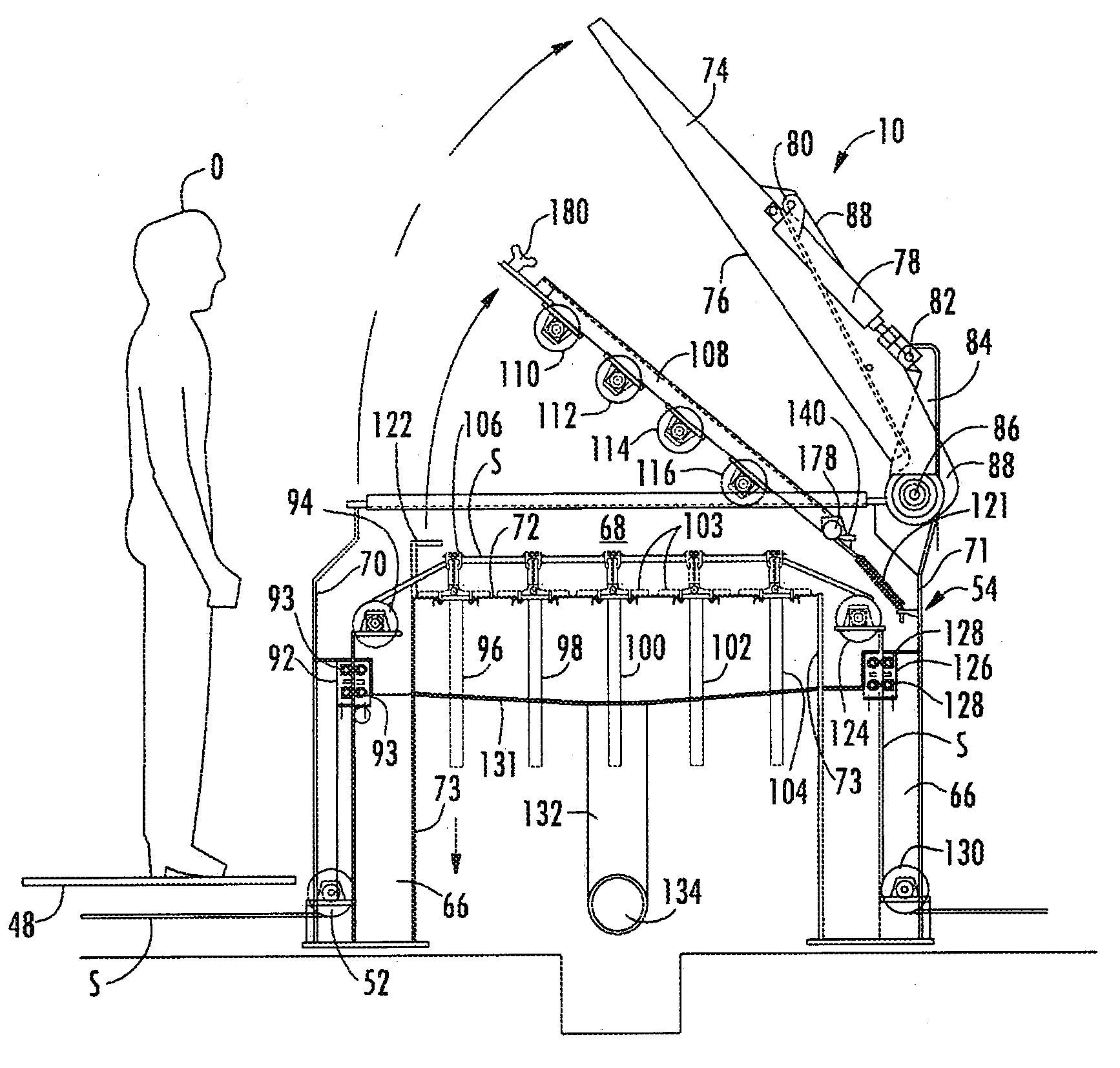
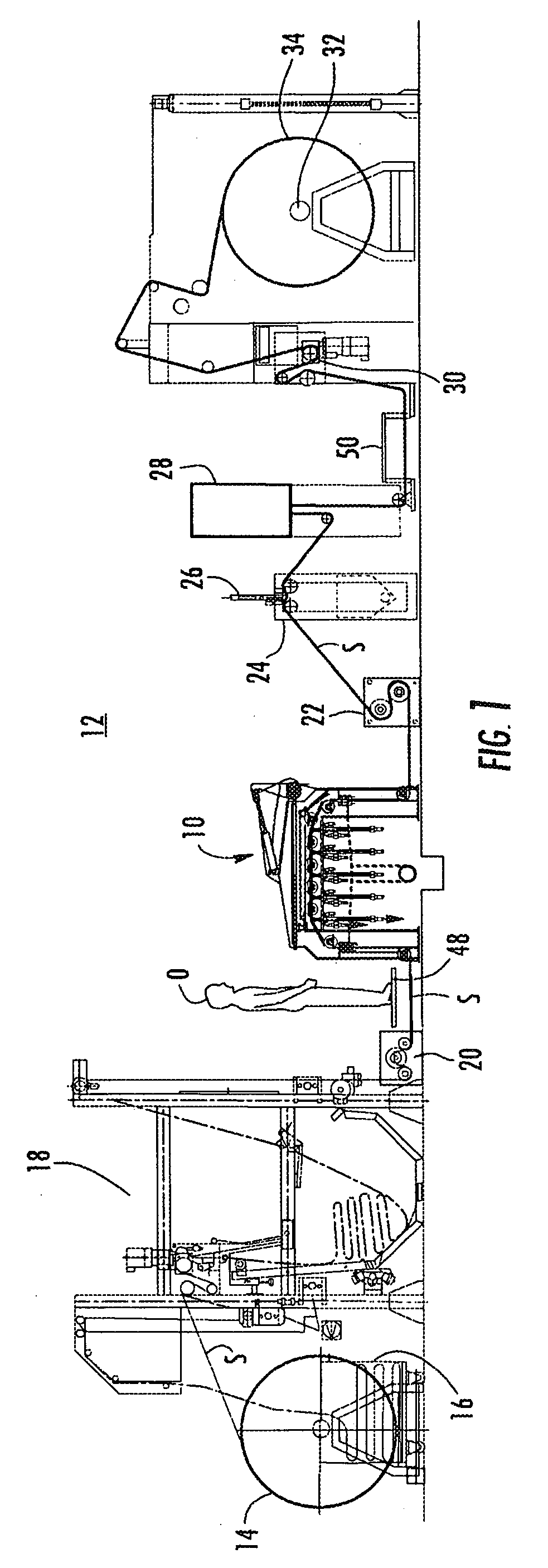
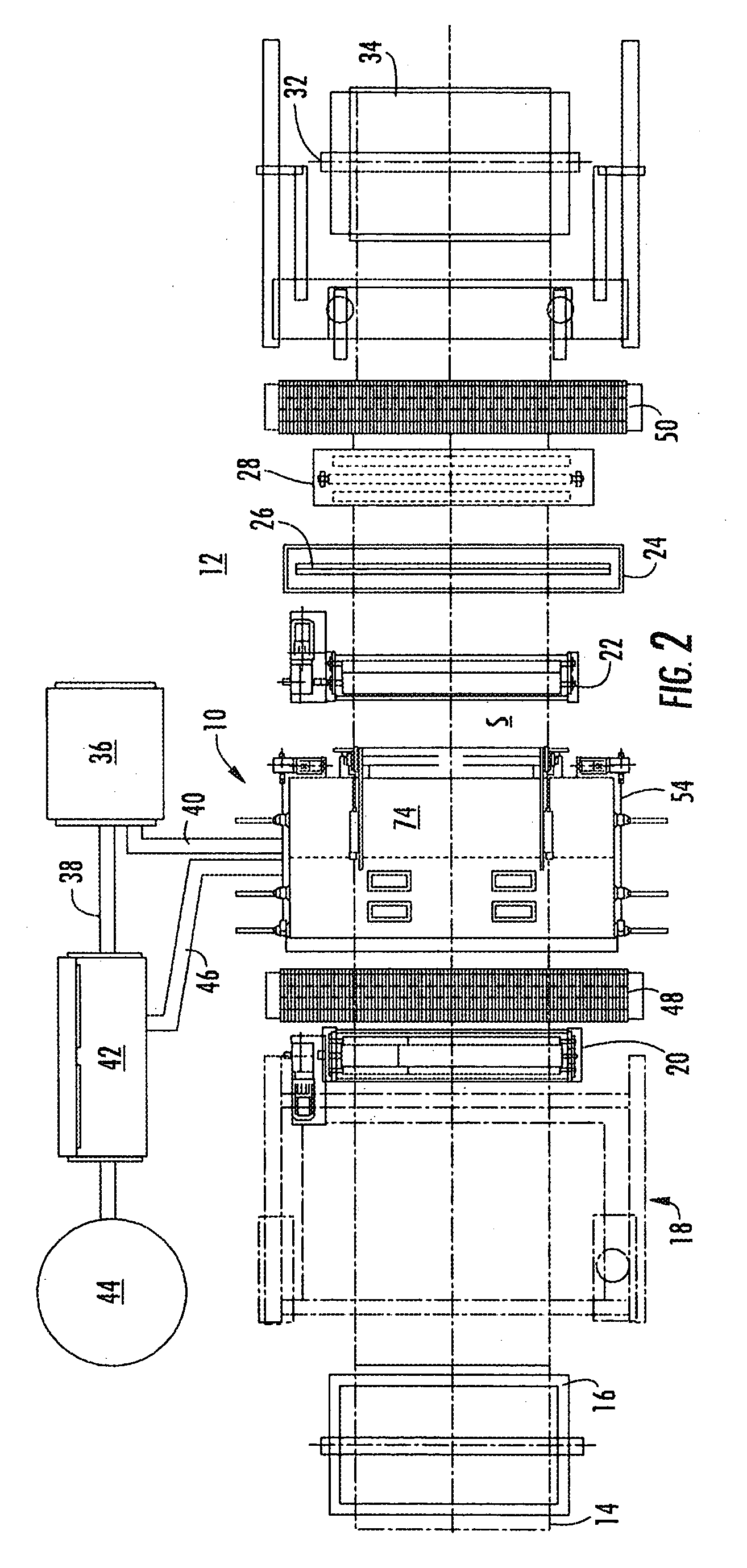
[0031]The dyeing apparatus 10 of one form of the preferred embodiment of the present invention is illustrated in FIGS. 1-8, of which FIGS. 1 and 2 illustrate the apparatus incorporated in a dyeing range 12. A sheet of textile substrate S is fed to the range 12 from a supply roll 14 or a supply of plaited material in a supply box 16. The substrate S is then relaxed in a J-box 18 from which it is withdrawn by a feed roll assembly 20 from which the substrate travels under a crosswalk grid 48 on which an observer O stands to monitor the dyeing operation in the dyeing apparatus 10. The substrate is drawn through the dyeing apparatus 10 by a driven pull roll assembly 22. The drive of the feed roll assembly 20 and pull roll assembly 22 are controlled so that a desired tension is being maintained in the substrate S as it travels through the apparatus 10. From the pull roll assembly 22 the substrate may be subjected to a supplemental treatment at a supplemental dye application station 24, at...


PUM


Abstract

An apparatus for dyeing a textile substrate using a plurality of applicators that each apply an increment of a total dye application. In one form a reduced indigo dye in a leuco-state is applied in an inert atmosphere substantially isolated from oxidizing substances. In another form the foamed dye is applied while open to the atmosphere. In both forms holddown rollers or inverted applicators are located between applicators at decreasing depths to minimize increases in tension as the substrate travels over successive applicator faces.

Description

[0001]This application is a continuation-in-part of pending U.S. patent application Ser. No. 11 / 805,893, filed May 25, 2007, published Nov. 22, 2007, as Publication No. 2007-0266505-A1, which is a continuation-in-part of U.S. patent application Ser. No. 10 / 833,450, filed Apr. 28, 2004, published Nov. 3, 2005, as Publication No. 2005-0241078-A1, now abandoned.BACKGROUND OF THE INVENTION[0002]The present invention relates to an apparatus for dyeing textile substrates with a foamed dye. In one form, the present invention relates to an apparatus for dyeing textile substrates containing cellulosic fibers with a reduced leuco-state dye foamed with an inert gas and applied in the leuco foamed state in an inert atmosphere to the textile substrate and subsequently oxidized thereon to affix the indigo dye to the cellulosic fibers of the textile substrate. In another form, the present invention relates to dyeing a textile fabric substrate with foamed dye applied incrementally by a plurality of...

Claims


Application Information

Patent Timeline
Patent Type & Authority Patents(United States)
IPC IPC(8): D06B3/10
CPCD06B19/0094D06B11/002D06B23/16
Inventor AURICH, CHRISTOPH WALTERZEIFFER, DIETER FRIEDRICHNEUPERT, HERMANN A.
Owner GASTON SYST INC
Why Eureka
Try Eureka