
Mechanical locking and deblocking device

An unlocking device and mechanical locking technology, which is applied in the field of mechanical devices, can solve the problems of increasing the total filling time, low reliability, cumbersome operation, etc., and achieve the effects of reducing filling time, high reliability, and easy assembly

Active Publication Date: 2014-01-22
GUIZHOU AEROSPACE TIANMA ELECTRICAL TECH
View PDF8 Cites 1 Cited by
  • Summary
  • Abstract
  • Description
  • Claims
  • Application Information

AI Technical Summary

Problems solved by technology

The lifting locking and unlocking device with the above structure is found to have the following two shortcomings during use: first, the mechanical and electrical combination method here makes the structure relatively complicated and the reliability is not high; second, because locking and unlocking take a certain time, And the operation is cumbersome, thus increasing the total filling time

Method used


Image

  • Mechanical locking and deblocking device
  • Mechanical locking and deblocking device
  • Mechanical locking and deblocking device

Examples


Embodiment Construction

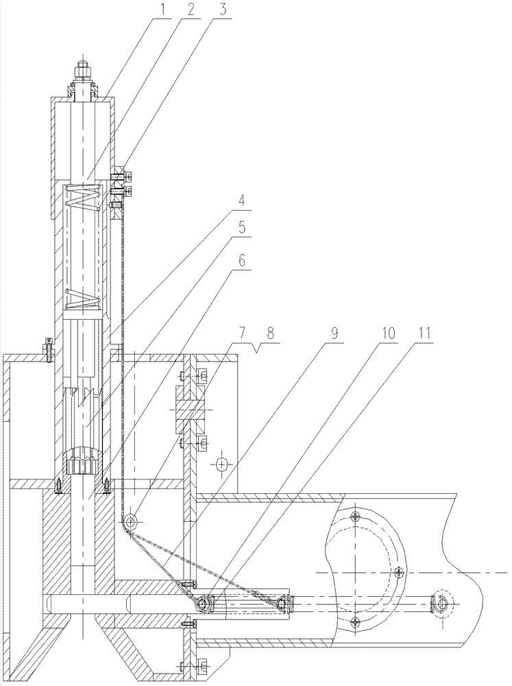
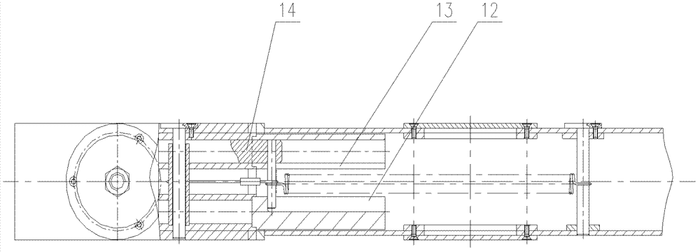
[0018] The mechanical locking and unlocking device of the present invention will be described in further detail below in conjunction with the accompanying drawings.

[0019] figure 1 , 2 Among them, a kind of mechanical locking and unlocking device of the present invention, its main part is made up of rod 2, push rod 6, lower guide rod 5, steel wire rope 9, lifting pin 14. When installing, insert the rod 2 and the push rod 6 into the lower guide rod 5 and make it fall to the bottom, the rod 2 is set above the push rod 6, one end of the wire rope 9 is fixed with the guide body 1, and the other end is connected with the lifting pin 14 .

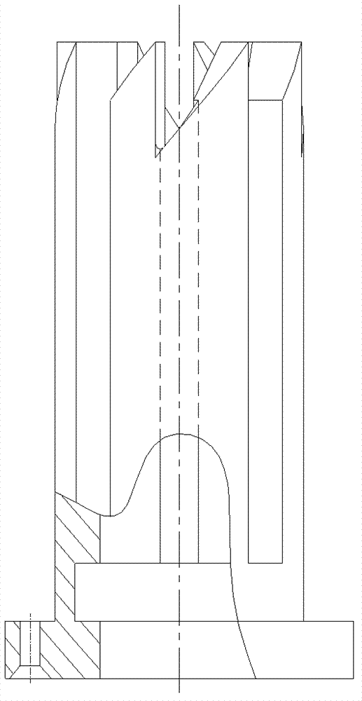
[0020] image 3 The shown lower guide rod 5 is fixed on the guide cylinder 4, and four deep grooves are arranged on its side, which are evenly distributed around the lower guide rod 5; The slots are connected.

[0021] Figure 4 The shown push rod 6 is contained in the lower guide rod 5, wherein one end of the polished rod is downward, an...


PUM


Abstract

The invention discloses a mechanical locking and deblocking device which comprises a guide body, a spring, a guide cylinder, a lower guide rod, a push rod, a drivepipe, a hoisting pin, a pin shaft, a spring, a sleeve, a rod and a steel wire rope, wherein one end of the steel wire rope is fixed on the guide body, and the other end of the steel wire rope is connected with the hoisting pin. The hoisting pin can automatically realize locking and hoisting hoisted objects, can automatically delock after the hoisting without additional locking and delocking process. The device has the characteristics of simple structure and high reliability, and is rapid in locking and delocking.

Description

technical field [0001] The invention relates to a mechanical locking and unlocking device, in particular to a mechanical device for hoisting locking and unlocking after hoisting on a special spreader for a transport and loading vehicle. Background technique [0002] The special spreader locking device for transport and loading vehicles initially adopts an electromechanical combination structure. When the special spreader is put in place, the motor starts to work, so that the lifting shafts at both ends of the spreader are stretched out until they are connected with the barrel bomb, and then the lifting is carried out. After the hoisting is completed, the motor rotates in reverse to retract the hoisting shaft. The lifting locking and unlocking device with the above structure is found to have the following two disadvantages during use: first, the mechanical and electrical combination method here makes the structure relatively complicated and the reliability is not high; second...

Claims


Application Information

Patent Timeline
Patent Type & Authority Patents(China)
IPC IPC(8): B66C1/10F16B1/04
Inventor 葛鹏熊伟超王曹华仲寻源
Owner GUIZHOU AEROSPACE TIANMA ELECTRICAL TECH
Learn More