
High-temperature cutting device for metal steel pipes and cutting method of high-temperature cutting device

A cutting device and a technology for steel pipes, applied in the field of metal steel pipes, can solve the problems of requiring labor, cumbersome use of the cutting device, and low work efficiency.

Inactive Publication Date: 2021-07-06
南京万鹏金属制品有限公司
View PDF10 Cites 0 Cited by
  • Summary
  • Abstract
  • Description
  • Claims
  • Application Information

AI Technical Summary

Problems solved by technology

[0004] The purpose of the present invention is to provide a high-temperature cutting device for metal steel pipes and a cutting method thereof, so as to solve the problem that the current cutting devices proposed in the above-mentioned background technology are mostly aimed at cutting a single steel pipe, and the cutting devices for cutting steel pipes in batches are relatively cumbersome to use and require Manual assisted work, low degree of automation, and low work efficiency

Method used


Image

  • High-temperature cutting device for metal steel pipes and cutting method of high-temperature cutting device
  • High-temperature cutting device for metal steel pipes and cutting method of high-temperature cutting device
  • High-temperature cutting device for metal steel pipes and cutting method of high-temperature cutting device

Examples


Embodiment Construction

[0032] The following will clearly and completely describe the technical solutions in the embodiments of the present invention with reference to the accompanying drawings in the embodiments of the present invention. Obviously, the described embodiments are only some, not all, embodiments of the present invention.

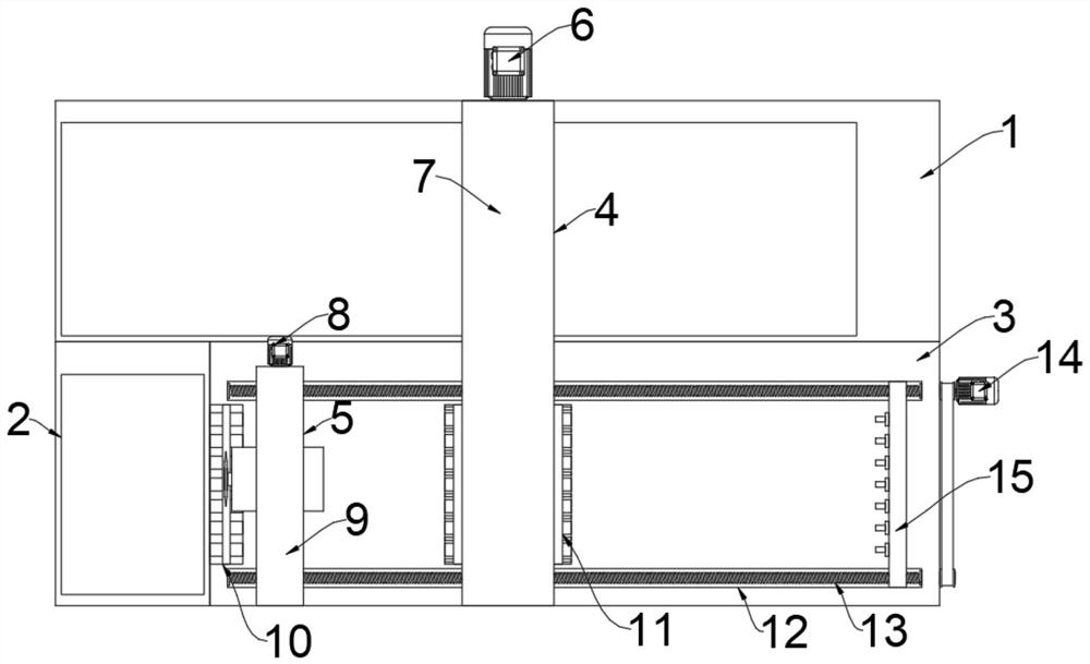
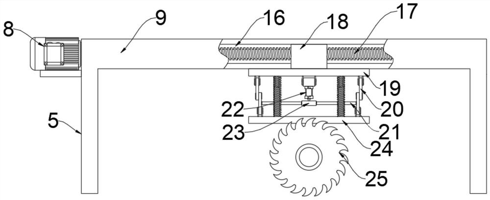
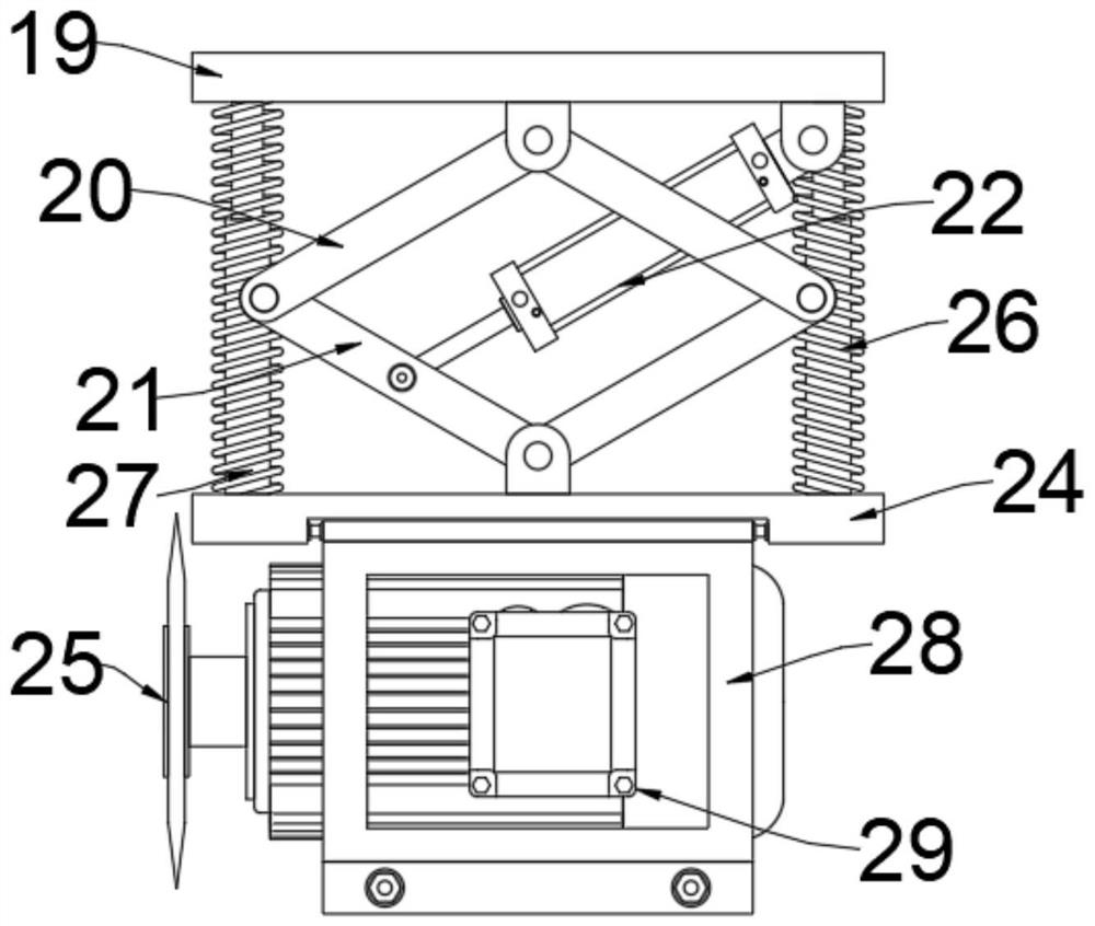
[0033] see Figure 1-7 , an embodiment provided by the present invention: a high-temperature cutting device for metal steel pipes, comprising a first storage box 1, a second storage box 2 is fixedly connected to one side of the front end of the first storage box 1, the first storage box The front end of the box 1 is fixedly connected with a support table 3 along one side of the second storage box 2, and the front and rear ends of the upper end of the support table 3 are provided with a first chute 12, and the inside of the first chute 12 is equipped with a first wire. Rod 13, a third drive motor 14 is installed along one side of the first screw mandrel 13 on the outs...


PUM


Abstract

The invention discloses a high-temperature cutting device for metal steel pipes and a cutting method of the high-temperature cutting device, relates to the related field of metal steel pipes, and aims to solve the problems that most of current cutting devices are used for cutting single steel pipes, and part of the cutting devices for cutting the steel pipes in batches are tedious in use process, need manual auxiliary work, are low in automation degree, and low in working efficiency. A second containing box is fixedly connected to one side of the front end of a first containing box, a supporting table top is fixedly connected to the front end of the first containing box along one side of the second containing box, first sliding grooves are formed in the front end and the rear end of the upper end face of the supporting table top, and first lead screws are installed in the first sliding grooves. A third driving motor is installed on the outer side of the supporting table top along one sides of the first lead screws, an alignment unit is arranged on one side of the upper end of the supporting table top and comprises a third C-shaped supporting frame, and third sliding blocks are fixedly connected to the two sides of the lower end of the third C-shaped supporting frame.

Description

technical field [0001] The invention relates to the related fields of metal steel pipes, in particular to a high-temperature cutting device for metal steel pipes and a cutting method thereof. Background technique [0002] Steel pipe (Steel pipe) is used to transport fluid and powdery solids, exchange heat, manufacture mechanical parts and containers, and is also an economical steel. The development of steel pipe production technology began with the rise of the bicycle manufacturing industry, the development of petroleum in the early 19th century, the manufacture of ships, boilers, and aircraft during the two world wars, the manufacture of thermal power boilers after the Second World War, the development of the chemical industry and Drilling, production and transportation of oil and natural gas have strongly promoted the development of steel pipe industry in terms of variety, output and quality. Steel pipes can be divided into two categories according to production methods: ...

Claims


Application Information

Patent Timeline
Patent Type & Authority Applications(China)
IPC IPC(8): B23D45/12B23D47/00B23D47/04B23D47/10
CPCB23D45/12B23D47/00B23D47/04B23D47/10
Inventor 何基龙
Owner 南京万鹏金属制品有限公司
Learn More